Lincoln Aviator: Driveshaft / Removal and Installation - Rear Driveshaft
Special Tool(s) / General Equipment
.jpg) |
100-001
(T50T-100-A)
Slide Hammer |
.jpg) |
205-832 Remover, Halfshaft TKIT-2006C-FFMFLM TKIT-2006C-LM TKIT-2006C-ROW |
| Slide Hammer | |
Materials
| Name | Specification |
|---|---|
| Motorcraft® Premium Long-Life Grease XG-1-E1 |
ESA-M1C75-B |
Removal
NOTE: The maximum articulation of the flex coupling is 4 degrees. The maximum articulation of any U-joint is 25 degrees. The maximum articulation of the center CV-joint is 20 degrees. The maximum articulation of the rear axle CV-joint is 15 degrees. If the flex coupling or any CV-Joint or U-joint of the driveshaft is articulated further than the maximum allowable degrees damage may occur.
NOTE: The following steps must be followed in the specified order or damage to driveshaft components may occur.
-
Remove the muffler and tailpipe.
Refer to: Muffler and Tailpipe (309-00A Exhaust System - 3.0L EcoBoost, Removal and Installation).
-
Remove the exhaust flexible pipe.
Refer to: Exhaust Flexible Pipe (309-00A Exhaust System - 3.0L EcoBoost, Removal and Installation).
-
If equipped.
Remove front air deflector assembly.
-
Remove the nuts and washers.
-
Remove a bolt.
-
Remove the push pins.
-
Remove the nuts.
-
Remove the nuts and washers.
.jpg) |
-
If equipped.
Remove front floor heat shield.
-
Remove the nuts and washers.
-
Remove a bolt.
-
Remove the screws and washers.
-
Remove the nuts and washers.
.jpg) |
-
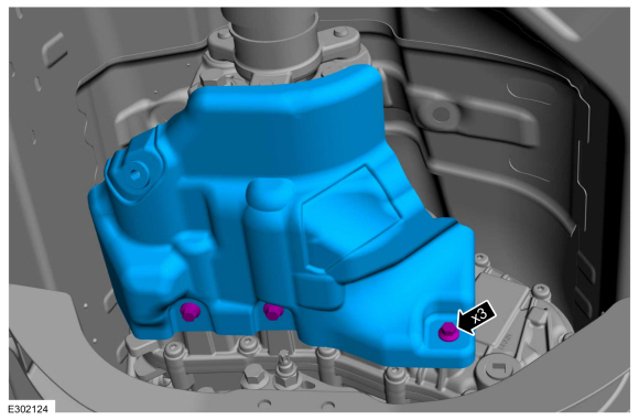
NOTICE: The help of a assistant may be needed. Do not over articulate the driveshaft or damage may occur.
Remove and discard the driveshaft center bearing bracket bolts.
.jpg) |
-
Remove the bolts and the transfer case heat shield.
 |
-
NOTICE: Do not over articulate the driveshaft or damage may occur.
Position aside and support the rear driveshaft.
-
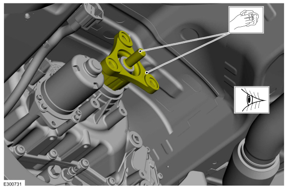
Mark the driveshaft flex coupling to the transfer case or transmission flange.
-
Remove and discard the driveshaft flex coupling to transfer case or transmission flange bolts.
-
Separate the flex coupling from the transfer case or transmission flange and support the driveshaft.
-
Mark the driveshaft flex coupling to the transfer case or transmission flange.
.jpg) |
-
-
Install the special tools to the rear CV-joint in the machined groove on the outer diameter of the CV-joint.
Use Special Service Tool: 205-832 Remover, Halfshaft. , 100-001 (T50T-100-A) Slide Hammer.
-
Using special tool, pull the rear CV-joint off of the rear axle pinion stem.
Use the General Equipment: Slide Hammer
-
Install the special tools to the rear CV-joint in the machined groove on the outer diameter of the CV-joint.
.jpg) |
-
NOTICE: Do not over articulate the driveshaft or damage may occur.
NOTE: This step requires the aid of another technician.
With the help from an assistant, remove the rear driveshaft from vehicle.
.jpg) |
-
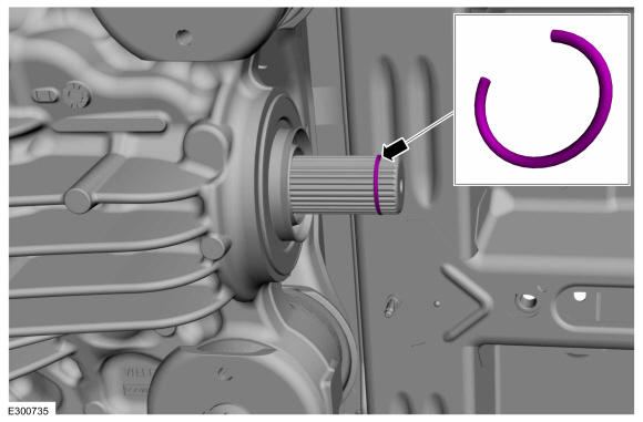
Remove and discard the rear axle pinion stem circlip.
.jpg) |
Installation
-
NOTE: Cracks forming in the flex coupling are normal.
Inspect the flex coupling for damage. If internal windings (threads) are visible, replace the flex coupling if required.
Refer to: Driveshaft Flexible Coupling (205-01 Driveshaft, Removal and Installation).
.jpg) |
-
Inspect the driveshaft alignment bushing for damage, clean the contamination. If required replace the same.
Refer to: Driveshaft Alignment Bushing (205-01 Driveshaft, Disassembly and Assembly).
.jpg) |
-
NOTE: Make sure that the threaded holes are clean and free of foreign matter.
NOTE: Make sure that the mating faces are clean and free of foreign material.
Clean and inspect the mating surfaces of driveshaft flexible coupling. Clean-off any contamination or excess grease off of transfer case or transmission flange and pilot spigot.
 |
-
NOTICE: Do not over lubricate the driveshaft components. Using excessive grease may damage the driveshaft components.
NOTE: Make sure that the mating faces are clean and free of foreign material.
Clean any contamination inside the driveshaft alignment bushing and lubricate the alignment bushing.
Material: Motorcraft® Premium Long-Life Grease / XG-1-E1 (ESA-M1C75-B)
.jpg) |
-
NOTE: Make sure that the mating faces are clean and free of foreign material.
Clean the contamination on the inner race sealing surface of the rear CV-joint.
.jpg) |
-
NOTICE: Do not over-lubricate the driveshaft components. Using excessive grease may damage the driveshaft components.
NOTE: Make sure that the mating faces are clean and free of foreign material.
Clean any contamination inside the rear CV-joint splines and lubricate the internal splines with grease.
Material: Motorcraft® Premium Long-Life Grease / XG-1-E1 (ESA-M1C75-B)
.jpg) |
-
NOTE: Make sure that the mating faces are clean and free of foreign material.
Clean any contamination on the rear axle pinion splines.
.jpg) |
-
NOTICE: The circlip must be side-loaded on to the rear axle pinion stem to prevent deformation of the circlip.
NOTE: Make sure that a new component is installed.
NOTE: Make sure that the circlip is installed correctly.
Install a new rear axle pinion stem circlip.
 |
-
-
Clean the contamination from the mounting surfaces of the underbody mating surfaces for the center bearing.
-
Clean the contamination from the mounting surfaces of the center bearing bracket mating surfaces.
-
Clean the contamination from the mounting surfaces of the underbody mating surfaces for the center bearing.
.jpg) |
-
NOTICE: The help of an assistant may be needed to support the driveshaft during attachment to the rear axle. Do not over articulate the driveshaft or damage may occur.
NOTE: If visible, align the yellow dot on the outer diameter of the rear driveshaft CV-joint to the yellow dot on the end of the rear axle pinion stem.
NOTE: When seating the rear driveshaft CV-joint to the rear axle, ONLY apply force to the rear CV-joint itself. DO NOT apply force from the front tube end of the driveshaft to seat the rear CV-joint to the rear axle.
NOTE: This step requires the aid of another technician.
Attach the special tools to the rear CV-joint in the machined groove on the outer diameter of the CV-joint as shown and impact the hammer to seat the rear CV-joint to the rear axle.
Use Special Service Tool: 205-832 Remover, Halfshaft. , 100-001 (T50T-100-A) Slide Hammer.
.jpg) |
-
NOTICE: Do not over articulate the driveshaft or damage may occur.
NOTE: Do not force the flex coupling bushing on the transfer case output shaft or damage will occur.
NOTE: Only tighten the bolts finger tight at this stage.
-
Align the index-mark on driveshaft flex coupling to the transfer case or transmission flange.
-
Install the new driveshaft flex coupling to transfer
case or transmission flange bolts and hand tighten at this stage.
-
Align the index-mark on driveshaft flex coupling to the transfer case or transmission flange.
.jpg) |
-
NOTE: Check that the slot position of the bolts is equal side to side of the center bearing before final securing of bolts. This will ensure the center bearing isolator is not twisted in the vehicle.
NOTE: Only tighten the bolts finger tight at this stage.
Mate the driveshaft center bearing to the underbody bracket and hand tighten the new driveshaft center bearing bracket bolts.
.jpg) |
-
NOTE: There is a casting parting line on the housing for reference of the centerline.
NOTE: Maintain a suitable distance between the components.
Ensure the distance from the CV-joint boot sheet metal can surface to machined aluminium surface of axle centerline.
.jpg) |
-
Tighten the driveshaft flex coupling to transfer case or transmission flange bolts.
Torque: 81 lb.ft (110 Nm)
.jpg) |
-
NOTICE: Ensure transfer case heatshield does not contact the driveshaft flex coupling.
Install the transfer case heat shield and the bolts.
Torque: 21 lb.ft (28 Nm)
|
-
Tighten the driveshaft center bearing bracket bolts.
Torque: 35 lb.ft (48 Nm)
.jpg) |
-
NOTICE: Do not over-lubricate the driveshaft components. Using excessive grease may damage the driveshaft components.
Clean the excess spline grease that is visible outside of the CV-joint to rear axle seal interface.
.jpg) |
-
If equipped.
Install front floor heat shield.
-
Install the nuts and washers.
Torque: 97 lb.in (11 Nm)
-
Install a bolt.
Torque: 22 lb.ft (30 Nm)
-
Install the screws and washers.
Torque: 22 lb.ft (30 Nm)
-
Install the nuts and washers.
|
-
If equipped.
Install the front air deflector assembly.
-
Install the nuts and washers.
Torque: 53 lb.in (6 Nm)
-
Install a bolt.
-
Install the push pins.
-
Install the nuts.
-
Install the nuts and washers.
|
-
Install the exhaust flexible pipe.
Refer to: Exhaust Flexible Pipe (309-00A Exhaust System - 3.0L EcoBoost, Removal and Installation).
-
Install the muffler and tailpipe.
Refer to: Muffler and Tailpipe (309-00A Exhaust System - 3.0L EcoBoost, Removal and Installation).
 Removal and Installation - Front Driveshaft Slip Yoke Boot
Special Tool(s) /
General Equipment
Crimping Tool
Removal
Remove the transfer case.
Remove and discard the boot clamp...
 Removal and Installation - Rear Driveshaft Slip Yoke Boot
Special Tool(s) /
General Equipment
Crimping Tool
Materials
Name
Specification
Motorcraft® Premium Long-Life GreaseXG-1-E1
ESA-M1C75-B
Removal
Remove the rear driveshaft...
Other information:
Lincoln Aviator 2020-2026 Service Manual: Diagnosis and Testing - Road Testing Vehicle
Shift Point Road Test NOTE: Always drive the vehicle in a safe manner according to driving conditions and obey all traffic laws. Upshift Gear Sequence At times the 10-speed transmission may skip gears when the vehicle starts from a complete stop...
Lincoln Aviator 2020-2026 Service Manual: Removal and Installation - Rear Evaporator Rear Outlet and Inlet Line
Removal All vehicles NOTICE: During the removal or installation of components, cap, tape or otherwise appropriately protect all openings and tubes/fittings to prevent the ingress of dirt or other contamination. Remove caps, tape and other protective materials prior to installation...
Categories
- Manuals Home
- Lincoln Aviator Owners Manual
- Lincoln Aviator Service Manual
- Configuring The Head Up Display
- Drive Modes
- Keyless Entry
- New on site
- Most important about car
Children and Airbags
WARNING: Airbags can kill or injure a child in a child restraint. Never place a rear-facing child restraint in front of an active airbag. If you must use a forward-facing child restraint in the front seat, move the seat upon which the child restraint is installed all the way back.
