Lincoln Aviator 2020-2026 Service Manual / Body and Paint / Body and Paint / Interior Trim and Ornamentation / Removal and Installation - Front Door Trim Panel
Lincoln Aviator: Interior Trim and Ornamentation / Removal and Installation - Front Door Trim Panel
Special Tool(s) / General Equipment
| Interior Trim Remover |
Removal
NOTE: LH (left hand) shown, RH (right hand) similar.
NOTE: Removal steps in this procedure may contain installation details.
-
Remove the appropriate door window control switch.
Refer to: Driver Door Window Control Switch (501-11 Glass, Frames and Mechanisms, Removal and Installation).
Refer to: Passenger Door Window Control Switch (501-11 Glass, Frames and Mechanisms, Removal and Installation).
-
Remove the front door trim panel upper bolt.
Torque: 48 lb.in (5.4 Nm)
.jpg) |
-
Remove the front door trim panel lower bolts.
Torque: 15 lb.in (1.7 Nm)
.jpg) |
-
Release the front door trim panel clips.
Use the General Equipment: Interior Trim Remover
.jpg) |
Left side
-
Release the front door latch emergency release cable.
-
Disengage the front door latch emergency release
cable from the front door latch emergency release handle.
-
Compress the front door latch emergency release cable tabs.
-
Slide the front door latch emergency release cable out the back.
-
Disengage the front door latch emergency release
cable from the front door latch emergency release handle.
.jpg) |
All vehicles
-
Remove the front door trim panel.
-
Lift upward and outward on the front door trim panel.
-
Disconnect the interior ambient light electrical connector.
-
Disconnect the seat control switch electrical connector.
-
Disconnect the front door tweeter speaker electrical connector.
-
If equipped.
Disconnect the front door mid range speaker electrical connector.
-
Lift upward and outward on the front door trim panel.
.jpg) |
Installation
-
To install, reverse the removal procedure.
 Removal and Installation - D-Pillar Trim Panel
Special Tool(s) /
General Equipment
Interior Trim Remover
Removal
NOTE:
LH shown, RH similar.
NOTE:
Removal steps in this procedure may contain installation details...
 Removal and Installation - Front Scuff Plate Trim Panel
Special Tool(s) /
General Equipment
Interior Trim Remover
Removal
NOTE:
LH (left hand) shown, RH (right hand) similar.
All sides
Release the clips and remove the instrument panel side trim panel...
Other information:
Lincoln Aviator 2020-2026 Service Manual: Removal and Installation - Rear Parking Aid Camera
Removal Remove the reversing lamp. Refer to: Reversing Lamp (417-01 Exterior Lighting, Removal and Installation). Disconnect the rear view camera washer hose and the rear view camera electrical connector. Remove the screw, the rear view camera bracket and the rear view camera/washer as an assembly...
Lincoln Aviator 2020-2026 Service Manual: Description and Operation - Vehicle Dynamic Suspension - Component Location
..
Categories
- Manuals Home
- Lincoln Aviator Owners Manual
- Lincoln Aviator Service Manual
- Wireless Accessory Charger (If Equipped)
- Child Safety Locks
- Fuel Quality
- New on site
- Most important about car
Activating Intelligent Access
The intelligent access key must be within 3 ft (1 m) of the door or luggage compartment you intend to lock or unlock.
At a Door
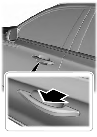
Electronic door handles are on each door. Gently depress the switch inside the exterior door handle to unlock and open the door. An unlock symbol illuminates on the door window trim indicating your vehicle is unlocked.

Copyright © 2026 www.liaviator2.com
