Lincoln Aviator: Interior Trim and Ornamentation / Removal and Installation - D-Pillar Trim Panel
Special Tool(s) /
General Equipment
Removal
NOTE:
LH shown, RH similar.
NOTE:
Removal steps in this procedure may contain installation details.
-
If equipped.
Remove the luggage compartment package cover.
-
Remove the luggage compartment floor covering.
-
Remove the luggage compartment spare tire cover.
-
Position the liftgate opening weatherstrip aside.
-
Remove the liftgate scuff plate trim panel.
-
Release the liftgate scuff plate trim panel clips.
Use the General Equipment: Interior Trim Remover
-
Disconnect the keyless entry rear antenna electrical connector.
-
NOTE:
LH shown, RH similar.
On both sides.
Release the clips and remove the luggage compartment side trim panel.
Use the General Equipment: Interior Trim Remover
-
Remove the third row seatbelt retractor anchor bolt and position seatbelt aside.
Torque:
35 lb.ft (47 Nm)
-
Position the liftgate opening weatherstrip aside.
-
Release the D-pillar trim panel clips.
-
Release the D-pillar trim panel side clip.
Use the General Equipment: Interior Trim Remover
-
Release the D-pillar trim panel front clips.
Use the General Equipment: Interior Trim Remover
-
NOTICE:
The D-pillar trim panel must be positioned downward
to allow the upper clip to release correctly. Failure to follow this
direction may cause damage to the D-pillar trim panel.
Slide the D-pillar trim panel down, aligning the upper clip to the slot in the sheet metal.
-
Release the D-pillar trim panel front clip.
Use the General Equipment: Interior Trim Remover
-
NOTICE:
The D-pillar trim panel must be positioned downward
to allow the upper clip to release correctly. Failure to follow this
direction may cause damage to the D-pillar trim panel.
Slide the D-pillar trim panel down, aligning the upper clip to the slot in the sheet metal.
-
Remove the D-pillar trim panel.
-
Pull outward on the D-pillar trim panel.
-
If equipped.
Disconnect the D-pillar speaker electrical connector.
-
Feed the third row seatbelt retractor through the opening in the D-pillar trim panel.
Installation
NOTE:
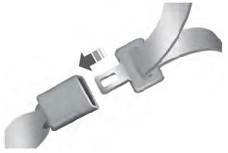
During installation, make sure the seatbelt webbing is not
twisted and the seatbelts and buckles are accessible to the occupants.
-
To install, reverse the removal procedure.
-
Check the seatbelt system for correct operation.
Refer to: Seatbelt Systems (501-20A Seatbelt Systems, Diagnosis and Testing).
Special Tool(s) /
General Equipment
Interior Trim Remover
Removal
NOTE:
LH (left hand) shown, RH (right hand) similar.
NOTE:
Removal steps in this procedure may contain installation details...
Special Tool(s) /
General Equipment
Interior Trim Remover
Removal
NOTE:
LH (left hand) shown, RH (right hand) similar.
NOTE:
Removal steps in this procedure may contain installation details...
Other information:
WARNING: To reduce the risk of
vehicle damage and personal burn injuries,
do not start your engine with the air
cleaner removed and do not remove it
while the engine is running.
When changing the engine air filter, do not
allow debris or foreign material to enter the
air induction system...
Removal
NOTICE:
Suspension fasteners are critical parts that affect the
performance of vital components and systems. Failure of these fasteners
may result in major service expense. Use the same or equivalent parts if
replacement is necessary. Do not use a replacement part of lesser
quality or substitute design...
.jpg)
.jpg)
.jpg)
.jpg)
.jpg)
.jpg)
.jpg)
.jpg)
.jpg)
.jpg)
.jpg)
.jpg)
.jpg)
 Removal and Installation - C-Pillar Trim Panel
 Removal and Installation - Front Door Trim Panel
