Lincoln Aviator: Front Suspension - AWD / Disassembly and Assembly - Shock Absorber and Spring Assembly
Special Tool(s) / General Equipment
| Spring Compressor | |
| Vise |
DISASSEMBLY
NOTICE: Suspension fasteners are critical parts that affect the performance of vital components and systems. Failure of these fasteners may result in major service expense. Use the same or equivalent parts if replacement is necessary. Do not use a replacement part of lesser quality or substitute design. Tighten fasteners as specified.
NOTE: Disassembly steps in this procedure may contain assembly details.
-
Remove the shock absorber and spring assembly.
Refer to: Shock Absorber and Spring Assembly (204-01A Front Suspension - RWD, Removal and Installation).
-
.jpg) WARNING:
Coil springs and strut assemblies are compressed
under extreme load. Always use a spring compressor for disassembly.
Follow procedure instructions carefully and make sure the spring
compressor has the correct spring plates or adapters. Failure to follow
these instructions may result in serious personal injury.
WARNING:
Coil springs and strut assemblies are compressed
under extreme load. Always use a spring compressor for disassembly.
Follow procedure instructions carefully and make sure the spring
compressor has the correct spring plates or adapters. Failure to follow
these instructions may result in serious personal injury.
NOTICE: When installing a suitable spring compressor, use care not to damage the spring coating.
NOTICE: Take extra care not to damage the component.
NOTICE: Do not use power tools to remove the nut.
Compress the coil spring enough to relieve the tension on the strut assembly.
Use the General Equipment: Spring Compressor
Use the General Equipment: Vise
.jpg) |
-
NOTE: Note the position of the components before removal.
NOTE: Do not use an impact wrench on the strut rod nut.
NOTE: Use the hex-holding feature to prevent the strut rod from turning while removing the strut rod nut.
Remove and discard the shock absorber and spring assembly rod nut. Disassemble the front shock absorber and spring assembly in the order shown.
.jpg) |
ASSEMBLY
-
NOTE: Make sure that the components are installed to the position noted before removal.
To assemble, reverse the disassembly procedure.
-
NOTE: Make sure that the spring is centered in the lower spring seat.
Make sure that the lower spring isolator pad is properly seated on spring seat.
.jpg) |
-
Press the jounce bumper into the top mount’s jounce
bumper cup. Make sure that jounce bumper groove is captured by the four
retention tabs during the assembly.
.jpg) |
-
NOTE: Make sure that the spring is correctly located in the lower spring isolator pad.
Make sure the components are correctly aligned during assembly. Ensure the coil spring is not resting on the vertical wall of the lower isolator pad.
.jpg) |
-
-
Make sure that the dust cover is clipped into all 12 tabs on the bearing.
-
Make sure that the dust cover is clipped into all 4 tabs on the shock absorber.
-
Make sure that the dust cover is clipped into all 12 tabs on the bearing.
.jpg) |
-
.jpg) WARNING:
Take extra care when handling a compressed spring.
Failure to follow this instruction may result in personal injury.
WARNING:
Take extra care when handling a compressed spring.
Failure to follow this instruction may result in personal injury.
NOTE: Make sure that the spring coating is not damaged during assembly process.
NOTE: Typical strut and spring assembly shown.
-
NOTE: Utilize the hex holding feature to prevent the strut rod from turning while installing the strut rod nut.
Install the new strut rod nut.
Use the General Equipment: Spring Compressor
Use the General Equipment: Vise
Torque: 41 lb.ft (55 Nm)
-
Install the cap.
-
.jpg) |
-
Install the shock absorber and spring assembly.
Refer to: Shock Absorber and Spring Assembly (204-01A Front Suspension - RWD, Removal and Installation).
 Removal and Installation - Wheel Studs
Special Tool(s) /
General Equipment
Hydraulic Press
Removal
NOTICE:
Suspension fasteners are critical parts that affect the
performance of vital components and systems...
 Disassembly and Assembly - Shock Absorber and Spring Assembly - Vehicles With: Air Suspension
Special Tool(s) /
General Equipment
Flat Headed Screw Driver
DISASSEMBLY
WARNING:
Vent all air pressure from the air suspension system prior
to disconnecting or removing any air suspension components...
Other information:
Lincoln Aviator 2020-2026 Owners Manual: About This Manual
Thank you for choosing Lincoln. We recommend that you take some time to get to know your vehicle by reading this manual. The more that you know about it, the greater the safety and pleasure you will get from driving it. WARNING: Driving while distracted can result in loss of vehicle control, crash and injury...
Lincoln Aviator 2020-2026 Owners Manual: Automatic Climate Control
Note: Depending on your vehicle option package, the controls may look different from what you see here. Note: You can switch temperature units between Fahrenheit and Celsius. Note: You can control some of the climate features through the touchscreen...
Categories
- Manuals Home
- Lincoln Aviator Owners Manual
- Lincoln Aviator Service Manual
- Anti-Theft Alarm
- Configuring The Head Up Display
- Tire Change Procedure
- New on site
- Most important about car
Activating Intelligent Access
The intelligent access key must be within 3 ft (1 m) of the door or luggage compartment you intend to lock or unlock.
At a Door
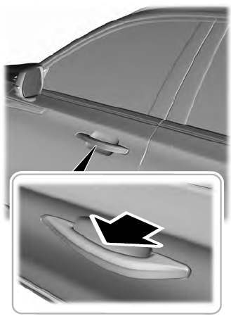
Electronic door handles are on each door. Gently depress the switch inside the exterior door handle to unlock and open the door. An unlock symbol illuminates on the door window trim indicating your vehicle is unlocked.

