Lincoln Aviator: Engine - 3.0L EcoBoost / Disassembly - Engine
Special Tool(s) /
General Equipment
.jpg) |
205-153
(T80T-4000-W)
Handle |
.jpg) |
303-1246
Engine Spreader Bar
TKIT-2006UF-FLM
TKIT-2006UF-ROW |
 |
303-1247
VCT Spark Plug Tube Seal Remover and Installer
TKIT-2006UF-FLM
TKIT-2006UF-ROW |
.jpg) |
303-1248
Camshaft holding tools
TKIT-2006UF-FLM
TKIT-2006UF-ROW |
.jpg) |
303-1634
Lift Eyes (2)
TKIT-2014D-ROW3
TKIT-2014D-FL_ROW |
.jpg) |
303-1696
Camshaft holding fixture |
.jpg) |
303-409
(T92C-6700-CH)
Remover, Crankshaft Seal
TKIT-1992-FH/FMH/FLMH
TKIT-1993-LMH/MH |
| Floor Crane |
| Mounting Stand |
| Plastic Scraper |
| Flat-Bladed Screwdriver |
Materials
| Name |
Specification |
Motorcraft® Silicone Gasket Remover
ZC-30-A |
-
|
Motorcraft® Metal Surface Prep Wipes
ZC-31-B |
-
|
Motorcraft® Metal Brake Parts Cleaner
PM-4-A, PM-4-B |
-
|
NOTICE:
During engine repair procedures, cleanliness is extremely
important. Any foreign material, including any material created while
cleaning gasket surfaces, that enters the oil passages, coolant passages
or the oil pan, can cause engine failure.
NOTICE:
The turbocharger compressor vanes can be damaged by even the
smallest particles. When removing any turbocharger or engine air intake
system component, ensure that no debris enters the system. Failure to do
so may result in damage to the turbocharger.
NOTICE:
Remove the cylinder heads before removing the crankshaft. Failure to do so can result in engine damage.
NOTE:
If the components are to be reinstalled, they must be installed
in their original location. Mark the components for installation into
their original location.
NOTE:
Refer to the exploded view under the Engine Component View in the Description and Operation.
LHD AWD/LHD RWD
-
Remove the bolts and the flexplate.
-
Remove the crankshaft sensor ring.
-
Inspect the crankshaft sensor ring for damage. If the
crankshaft sensor ring has been dropped or has any visual damage, it
must be discarded.
-
Remove the nut and the heat shield.
-
-
Disconnect the CKP sensor electrical connector.
-
Remove the stud bolt and the CKP sensor.
-
Remove the bolts and the crankshaft rear seal and retainer plate.
-
Discard the crankshaft rear seal and retainer plate.
-
NOTICE:
Do not use metal scrapers, wire brushes, power
abrasive discs or other abrasive means to clean the sealing surfaces.
These tools cause scratches and gouges which make leak paths. Use a
plastic scraping tool to remove all traces of old sealant.
Clean and inspect the mating surface.
Refer to: RTV Sealing Surface Cleaning and Preparation (303-00 Engine System - General Information, General Procedures).
Use the General Equipment: Plastic Scraper
Material: Motorcraft® Silicone Gasket Remover
/ ZC-30-A
Material: Motorcraft® Metal Brake Parts Cleaner
/ PM-4-A, PM-4-B
Material: Motorcraft® Metal Surface Prep Wipes
/ ZC-31-B
-
Using a floor crane, install the engine on a mounting stand.
Remove Special Service Tool: 303-1246
Engine Spreader Bar.
, 303-1634
Lift Eyes (2).
Use the General Equipment: Floor Crane
Use the General Equipment: Mounting Stand
-
-
Remove the bolts and the LH engine mount.
-
NOTE:
AWD shown, RWD similar.
-
Remove and discard the nuts and bolts.
-
Remove the RH engine mount.
-
NOTE:
AWD shown, RWD similar.
Remove and discard the studs.
LHD RWD
-
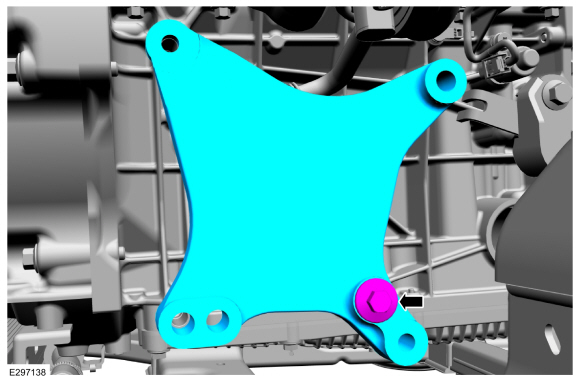
Remove the bolt and the engine mount spacer.
LHD AWD
-
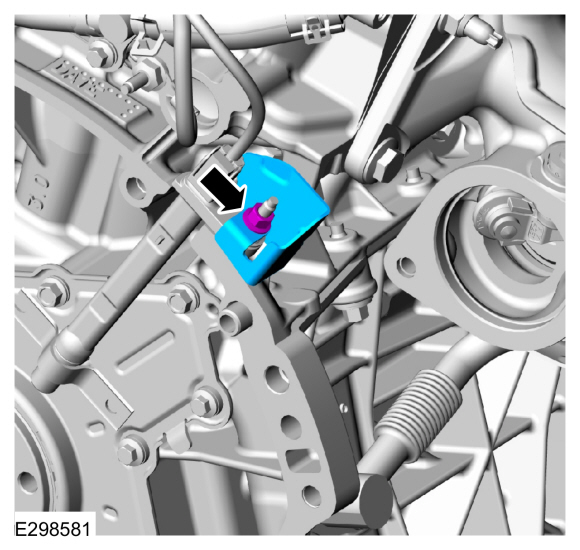
Remove the bolts and the front axle disconnect actuator.
-
Remove and discard the seal.
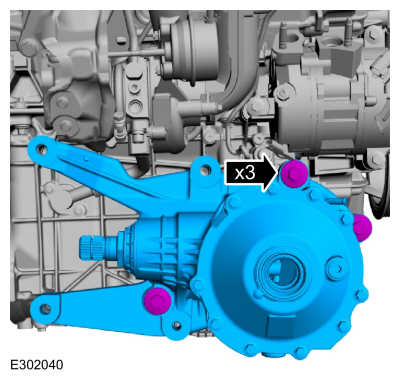
-
Remove the bolts and the front axle assembly.
-
Remove and discard the front axle assembly seal.
LHD AWD/LHD RWD
-
Remove the oil level indicator.
-
-
Detach the fuel tube retainer.
-
Disconnect the quick release coupling and remove the fuel tube assembly.
Refer to: Quick Release Coupling (310-00A Fuel System - General Information - 3.0L EcoBoost, General Procedures).
-
Disconnect the quick release coupling and remove the EVAP tube.
Refer to: Quick Release Coupling (310-00A Fuel System - General Information - 3.0L EcoBoost, General Procedures).
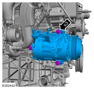
-
Remove the bolts and the A/C compressor.
-
Remove the bolts and the air cleaner outlet pipe.
-
Inspect the O-ring seal and replace as necessary.
-
-
Detach the wiring harness retainer.
-
Loosen the clamp and remove the CAC inlet pipe.
-
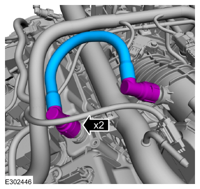
Disconnect the quick release couplings and remove the crankcase vent tube.
Refer to: Quick Release Coupling (310-00A Fuel System - General Information - 3.0L EcoBoost, General Procedures).
-
-
Remove the stud bolt and the ground wire.
-
Slide the wiring harness insulator up.
-
Disconnect the CHT electrical connector.
-
-
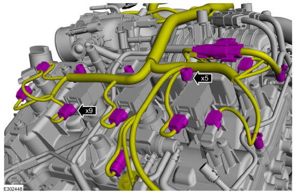
Disconnect the wiring harness electrical connectors.
-
Detach the wiring harness retainers.
-
-
Disconnect the wiring harness electrical connectors.
-
Detach the wiring harness retainers.
-
-
Remove the stud bolt and the ground wire from the rear of the RH cylinder head.
-
Detach the wiring harness retainer.
-
-
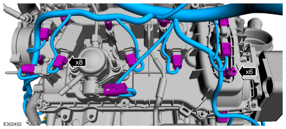
Disconnect the wiring harness electrical connectors.
-
Detach the wiring harness retainers.
-
-
Disconnect the wiring harness electrical connectors.
-
Detach the wiring harness retainers.
-
Remove the wiring harness from the engine.
-
-
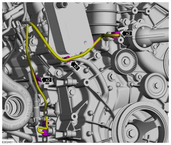
Release the clamp and disconnect the vacuum hose.
-
Detach the vacuum harness retainer.
-
Disconnect the vacuum harness quick release coupling.
Refer to: Quick Release Coupling (310-00A Fuel System - General Information - 3.0L EcoBoost, General Procedures).
-
-
Detach the vacuum harness retainers.
-
Remove the vacuum harness from the engine.
-
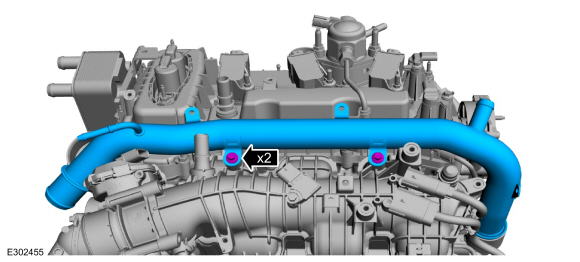
Remove the bolts and the coolant pipe.
-
Inspect the O-ring seal and replace as necessary.
-
Loosen the bolts and remove the intake manifold.
-
-
Remove and inspect the gaskets, replace as necessary.
-
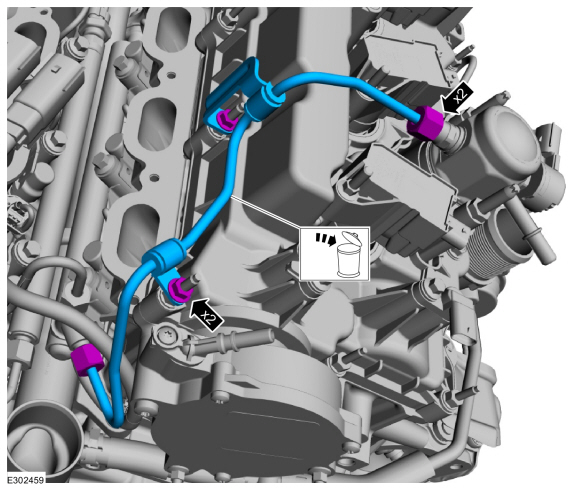
NOTICE:
To release the fuel pressure in the high-pressure
fuel tube, wrap the high-pressure fuel tube flare nuts with a shop towel
to absorb any residual fuel pressure during the loosening of
high-pressure fuel tube flare nuts.
-
Loosen the fuel tube flare nut fittings.
-
Remove and discard the fuel tube.
-
NOTE:
Alternately loosen the high-pressure fuel pump nuts one revolution at a time.
Remove the nuts and the high-pressure fuel pump.
-
Remove and discard the high-pressure fuel pump O-ring seal.
-
Remove the high-pressure fuel pump tappet.
-
Inspect the high-pressure fuel pump roller tappet. If
any flat spots or scoring are found, especially in the indicated areas,
then inspect the high-pressure fuel pump and the high-pressure fuel pump
roller tappet drive lobe. Install new components as necessary.
-
If damaged, remove and discard the studs.
-
Remove the fasteners and the TC oil return tube.
-
Remove and discard the TC oil return tube tube-to-engine block gasket.
-
Remove and discard the TC oil return tube O-ring seal.
-
NOTICE:
Inspect for blockage in the turbocharger tube. Check
the tube, the sealing surfaces and the flange for flatness and damage.
Ensure that the retaining bracket is not bent, check for square-ness of
the retaining bracket to the O-ring area. Use brake cleaner and a NYLON
brush to clean. DO NOT USE A METAL BRUSH; DAMAGE TO SEALING AREA WILL
RESULT IN LEAKS.
Clean and inspect the TC oil return tube.
Material: Motorcraft® Metal Brake Parts Cleaner
/ PM-4-A, PM-4-B
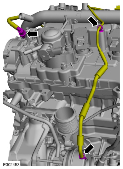
-
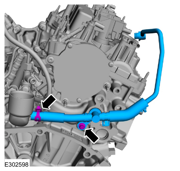
Remove the TC coolant return tube bolt.
-
-
Remove the TC oil supply tube bolt.
-
Remove the TC coolant supply tube bolt.
-
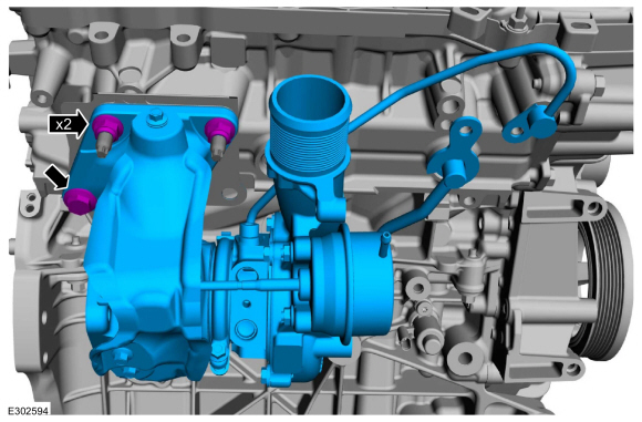
Remove the fasteners and the TC.
-
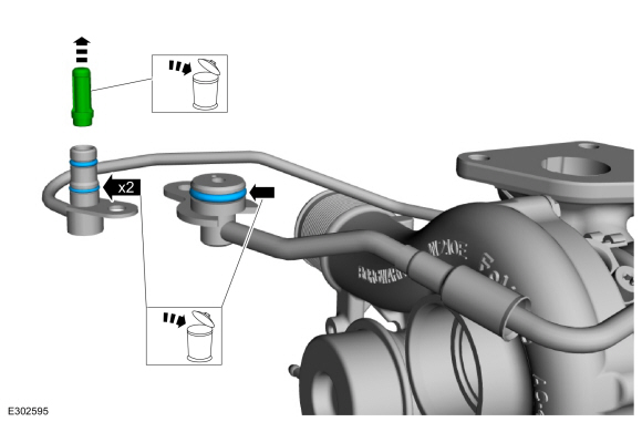
-
Remove and discard the TC oil supply tube filter and O-ring seals.
-
Remove and discard the TC coolant supply tube O-ring seal.
-
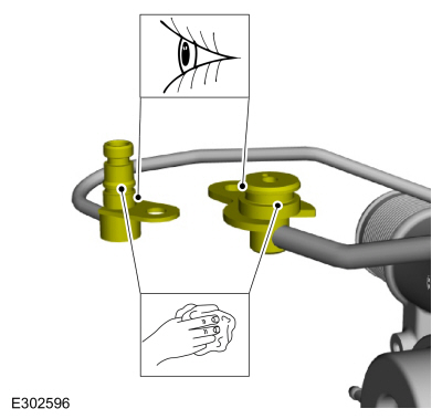
NOTICE:
Inspect the turbocharger tubes and the sealing
surfaces. Ensure that the retaining brackets are not bent, check for
square-ness of the retaining brackets to the O-ring areas. Use brake
cleaner and a NYLON brush to clean. DO NOT USE A METAL BRUSH; DAMAGE TO
SEALING AREA WILL RESULT IN LEAKS.
-
Clean and inspect the TC oil supply tube.
Material: Motorcraft® Metal Brake Parts Cleaner
/ PM-4-A, PM-4-B
-
Clean and inspect the TC coolant supply tube.
Material: Motorcraft® Metal Brake Parts Cleaner
/ PM-4-A, PM-4-B
-
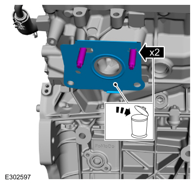
-
Remove and discard the TC gasket.
-
If damaged, remove and discard the TC stud(s).
-
-
Release the clamp and remove the TC coolant return tube.
-
Remove and discard the O-ring seals.
-
NOTICE:
Inspect the turbocharger tube and the sealing
surfaces. Ensure that the retaining bracket is not bent, check for
square-ness of the retaining brackets to the O-ring area. Use brake
cleaner and a NYLON brush to clean. DO NOT USE A METAL BRUSH; DAMAGE TO
SEALING AREA WILL RESULT IN LEAKS.
Clean and inspect the TC coolant return tube fitting.
Material: Motorcraft® Metal Brake Parts Cleaner
/ PM-4-A, PM-4-B
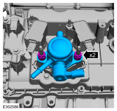
-
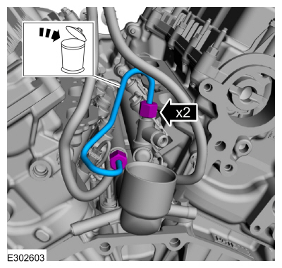
Remove the fasteners and the vacuum pump.
-
-
Release the clamp and remove the TC coolant return tube.
-
Remove and discard the O-ring seal.
-
-
Loosen the fuel tube flare nut fittings.
-
Remove and discard the fuel tube
-
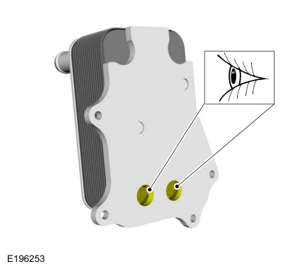
Remove the bolts and the oil cooler.
-
Inspect the oil cooler. If metal or aluminum material is
present in the oil cooler, mechanical concerns exist. Failure to
correct these concerns may cause engine failure.
Refer to: Engine (303-00 Engine System - General Information, Diagnosis and Testing).
-
Remove and discard the oil cooler gasket.
-
-
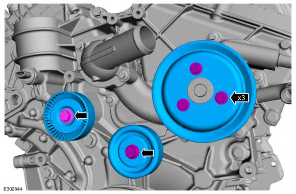
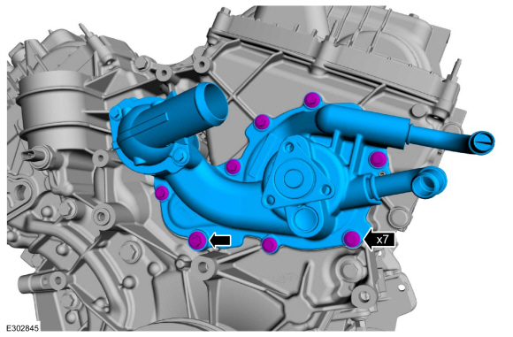
Remove the bolts and the coolant pump pulley.
-
Remove the bolt and the idler pulley.
-
Remove the bolt and the idler pulley.
-
Remove the bolts and the coolant pump.
-
Remove and discard the coolant pump gasket and seal.
-
NOTE:
When removing the ignition coil-on-plugs, a slight twisting motion will break the seal and ease removal.
Remove the stud bolts and the LH ignition coil-on-plugs.
-
NOTE:
When removing the ignition coil-on-plugs, a slight twisting motion will break the seal and ease removal.
Remove the stud bolts and the RH ignition coil-on-plugs.
-
Remove the nuts and the bracket.
-
Loosen the fasteners and remove the valve cover.
-
-
Remove and discard the gaskets.
-
Clean the valve cover gasket groove with soap and water or a suitable solvent.
-
Inspect the spark plug seals. Remove any damaged seals using the special tools.
Use Special Service Tool: 205-153
(T80T-4000-W)
Handle.
, 303-1247
VCT Spark Plug Tube Seal Remover and Installer.
-
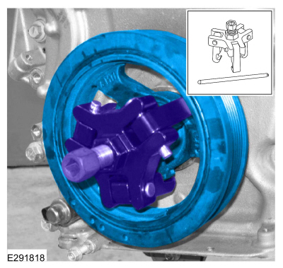
Remove the crankshaft pulley bolt.
-
NOTE:
Use a universal puller (such as an OTC 6667, or equivalent).
Using a universal puller, remove the crankshaft pulley.
-
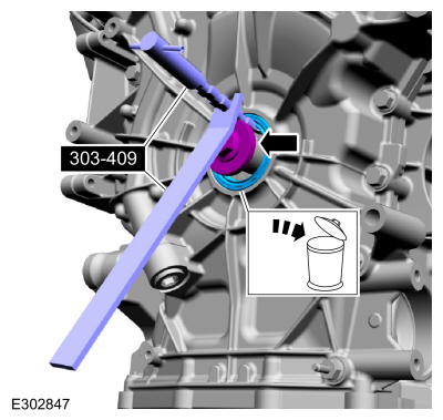
NOTICE:
Use care not to damage the engine front cover or the crankshaft when removing the seal.
-
Install the crankshaft pulley bolt.
-
Using the special tool, remove and discard the crankshaft front oil seal.
Use Special Service Tool: 303-409
(T92C-6700-CH)
Remover, Crankshaft Seal.
-
NOTE:
Retain the original crankshaft pulley bolt for turning the crankshaft while the pulley is removed.
Remove the crankshaft pulley bolt.
-
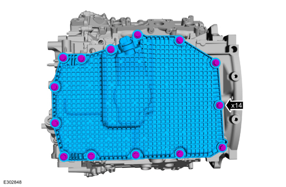
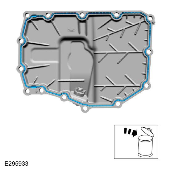
Remove the bolts and the oil pan.
-
Remove and discard the oil pan gasket.
-
NOTICE:
Do not use metal scrapers, wire brushes, power
abrasive discs or other abrasive means to clean the sealing surfaces.
These tools cause scratches and gouges, which make leak paths. Use a
plastic scraping tool to remove traces of sealant.
Make sure that the mating faces of the engine block and
engine front cover are clean and free of foreign material.
-
NOTE:
There are 5 different types of fasteners, note location of each fastener for assembly.
Remove the engine front cover fasteners.
-
Using a large flat-bladed screwdriver and the indicated
pry pads, release the sealer and remove the engine front cover.
Use the General Equipment: Flat-Bladed Screwdriver
-
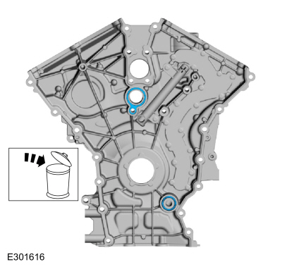
Remove and discard the engine front cover gaskets.
-
Remove and discard the oil gallery seal (6G068).
-
NOTICE:
Only use a 3M™ Roloc® Bristle Disk (2-in white, part
number 07528) to clean the engine front cover. Do not use metal
scrapers, wire brushes or any other power abrasive disk to clean front
cover.
-
Clean the engine front cover using a 3M™ Roloc®
Bristle Disk (2-in white, part number 07528) in a suitable tool turning
at the recommended speed of 15,000 rpm.
Refer to: RTV Sealing Surface Cleaning and Preparation (303-00 Engine System - General Information, General Procedures).
-
Thoroughly wash the engine front cover to remove any
foreign material, including any abrasive particles created during the
cleaning process.
Material: Motorcraft® Silicone Gasket Remover
/ ZC-30-A
Material: Motorcraft® Metal Brake Parts Cleaner
/ PM-4-A, PM-4-B
Material: Motorcraft® Metal Surface Prep Wipes
/ ZC-31-B
.jpg) |
|
-
NOTICE:
Place clean, lint-free shop towels over exposed
engine cavities. Carefully remove the towels so foreign material is not
dropped into the engine. Any foreign material (including any material
created while cleaning gasket surfaces) that enters the oil passages may
cause engine failure.
NOTICE:
Do not use wire brushes, power abrasive discs or 3M™
Roloc® Bristle Disk (2-in white part number 07528) to clean the sealing
surfaces. These tools cause scratches and gouges that make leak paths.
They also cause contamination that will cause premature engine failure.
Remove all traces of the gasket.
Make sure that the mating faces of the engine block are clean and free of foreign material.
Refer to: RTV Sealing Surface Cleaning and Preparation (303-00 Engine System - General Information, General Procedures).
Use the General Equipment: Plastic Scraper
Material: Motorcraft® Silicone Gasket Remover
/ ZC-30-A
Material: Motorcraft® Metal Brake Parts Cleaner
/ PM-4-A, PM-4-B
Material: Motorcraft® Metal Surface Prep Wipes
/ ZC-31-B
.jpg) |
|
-
NOTICE:
Rotate the crankshaft utilizing only the original
crankshaft pulley bolt. Failure to follow this direction may cause
damage to the crankshaft and result in engine failure.
Install the original crankshaft pulley bolt.
-
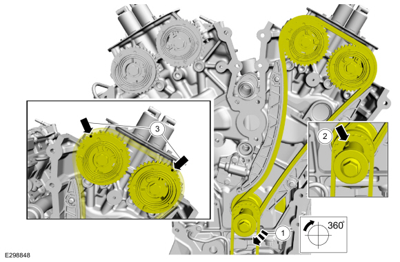
NOTICE:
The VCT units have 2 timing marks on them, a triangle and a circle. For removal and installation of the RH side the triangle marks are used.
-
Rotate the crankshaft clockwise.
-
Position the crankshaft sprocket keyway at the 11 o'clock position.
-
Verify the triangle timing marks on the VCT units are at the 2 o'clock (intake) and 11 o'clock (exhaust) positions. If the circle timing marks are at these positions the crankshaft must be turned clockwise one revolution (360 degrees).
-
Remove the bolts and the RH timing chain tensioner.
-
Remove the RH timing chain tensioner arm.
-
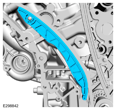
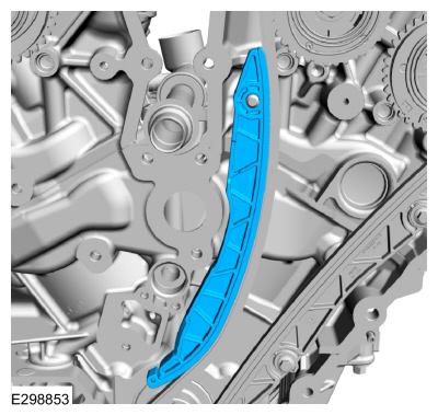
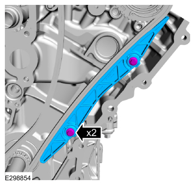
Remove the bolts and the RH timing chain guide.
-
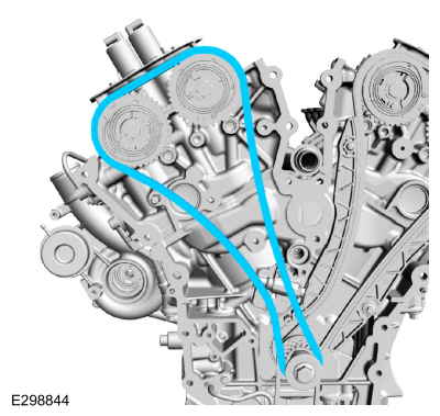
Remove the RH timing chain.
-
NOTICE:
The crankshaft must be rotated clockwise one
revolution (360 degrees). Failure to do so will result in incorrect
camshaft timing.
NOTICE:
The VCT units have 2 timing marks on them, a triangle and a circle. For removal and installation of the LH side the circle marks are used.
-
Rotate the crankshaft clockwise one revolution (360 degrees).
-
Position the crankshaft sprocket keyway at the 11 o'clock position.
-
The circle timing marks on the VCT units will be at the 10 o'clock (intake) and 12:30 (exhaust) positions.
-
Remove the original crankshaft pulley bolt.
-
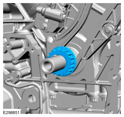
Remove the timing chain sprocket.
-
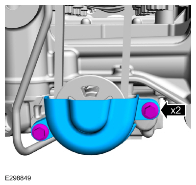
Remove the bolts and the splash shield.
-
Slide the oil pump drive belt off of the crankshaft sprocket and remove the belt.
-
Remove the crankshaft sprocket.
-
Remove the bolts and the LH timing chain tensioner.
-
Remove the LH timing chain tensioner arm.
-
Remove the bolts and the LH timing chain guide.
-
Remove the LH timing chain.
-
Remove the timing chain sprocket.
-
-
Remove the bolts and the oil return tube,
-
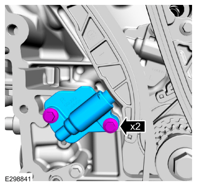
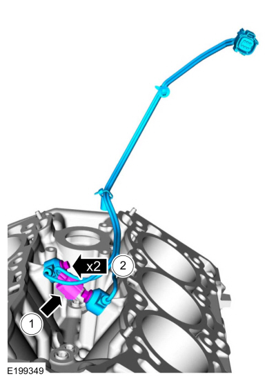
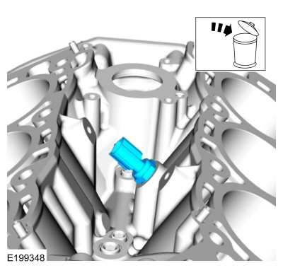
Remove the bolt and the oil control solenoid.
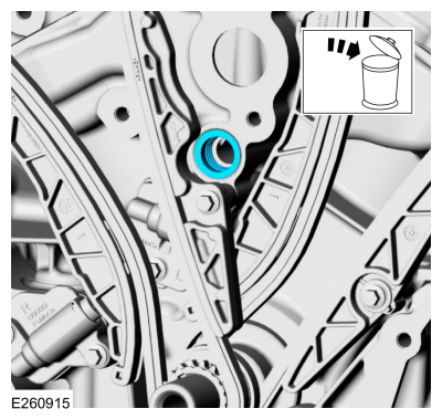
-
Remove and discard the O-ring seals.
-
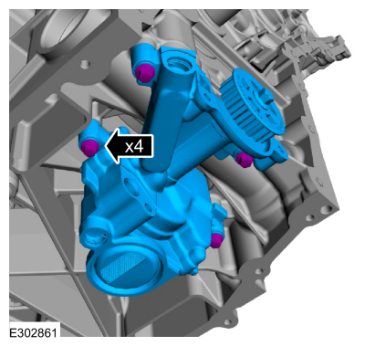
Remove the bolts and the oil pump.
-
-
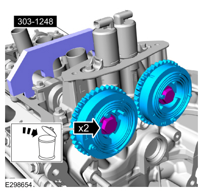
Install Special Service Tool: 303-1696
Camshaft holding fixture.
-
Remove and discard the VCT unit bolts.
-
Remove the VCT units.
-
Remove Special Service Tool: 303-1696
Camshaft holding fixture.
-
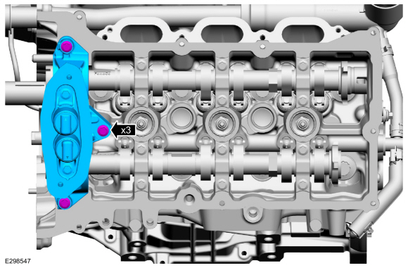
NOTICE:
The front camshaft bearing mega cap must be removed
first and then the remaining camshaft bearing caps. Failure to follow
this direction may result in damage to the engine.
Remove the bolts and the front camshaft bearing mega cap.
-
Remove the bolts and the camshaft bearing caps.
-
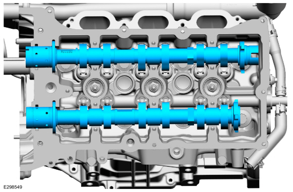
Remove the intake and exhaust camshafts.
-
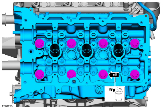
-
Remove the camshaft roller follower and hydraulic lash adjuster assemblies.
-
Separate the hydraulic lash adjusters from the spring clips on the camshaft roller followers.
-
Inspect the hydraulic lash adjuster and roller
follower for damage. If any damage is found, inspect the camshaft lobes
and valves for damage. Replace damaged components as necessary.
-
-
Remove and discard the cylinder head bolts.
-
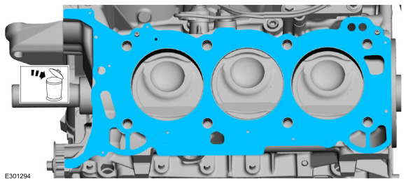
Remove the cylinder head.
-
Remove and discard the cylinder head gasket.
-
-
Clean and inspect the cylinder head-to-cylinder
block mating surfaces of both the cylinder head and the cylinder block.
-
Refer to: Cylinder Head Distortion (303-00 Engine System - General Information, General Procedures).
-
Refer to: Cylinder Block Distortion (303-00 Engine System - General Information, General Procedures).
-
-
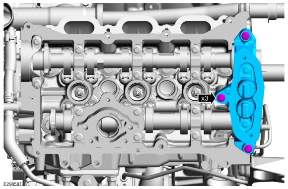
Install Special Service Tool: 303-1248
Camshaft holding tools.
-
Remove and discard the VCT unit bolts.
-
Remove the VCT units.
-
Remove Special Service Tool: 303-1248
Camshaft holding tools.
-
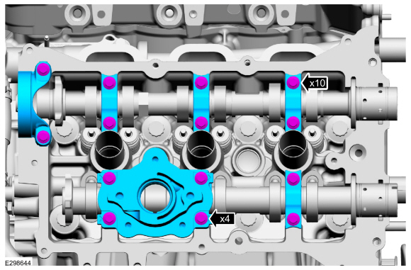
NOTICE:
The front camshaft bearing mega cap must be removed
first and then the remaining camshaft bearing caps. Failure to follow
this direction may result in damage to the engine.
Remove the bolts and the front camshaft bearing mega cap.
-
Remove the bolts and the camshaft bearing caps.
-
Remove the intake and exhaust camshafts.
-
-
Remove the camshaft roller follower and hydraulic lash adjuster assemblies.
-
Separate the hydraulic lash adjusters from the spring clips on the camshaft roller followers.
-
Inspect the hydraulic lash adjuster and roller
follower for damage. If any damage is found, inspect the camshaft lobes
and valves for damage. Replace damaged components as necessary.
-
-
Remove and discard the cylinder head bolts.
-
Remove the cylinder head.
-
Remove and discard the cylinder head gasket.
-
-
Clean and inspect the cylinder head-to-cylinder
block mating surfaces of both the cylinder head and the cylinder block.
-
Refer to: Cylinder Head Distortion (303-00 Engine System - General Information, General Procedures).
-
Refer to: Cylinder Block Distortion (303-00 Engine System - General Information, General Procedures).
-
-
Detach the wiring harness retainer from the stud bolt
-
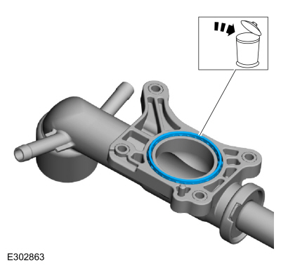
Remove the stud bolt, the nuts and the coolant outlet connector pipe.
-
Remove and discard the coolant outlet connector pipe gasket.
-
-
Disconnect the ECT sensor electrical connector.
-
Remove the bolts and the KS assembly.
-
NOTE:
Do not reuse the ECT sensor, install a new sensor.
Remove and discard the ECT sensor.
-
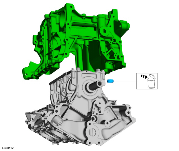
Remove the engine block skirt stiffener bolts.
-
Using a suitable pry bar at the pry pad locations,
release the engine block skirt stiffener-to-engine block seal.
-
-
Remove the engine block skirt stiffener.
-
Remove and discard the oil seal.
-
NOTICE:
Do not use metal scrapers, wire brushes, power
abrasive discs or other abrasive means to clean the sealing surfaces.
These tools cause scratches and gouges which make leak paths. Use a
plastic scraping tool to remove all traces of old sealant.
Clean and inspect the mating surfaces.
Refer to: RTV Sealing Surface Cleaning and Preparation (303-00 Engine System - General Information, General Procedures).
Use the General Equipment: Plastic Scraper
Material: Motorcraft® Silicone Gasket Remover
/ ZC-30-A
Material: Motorcraft® Metal Brake Parts Cleaner
/ PM-4-A, PM-4-B
Material: Motorcraft® Metal Surface Prep Wipes
/ ZC-31-B
-
-
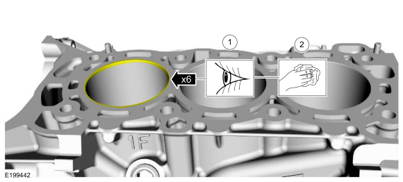
Before removing the pistons, inspect the top of the cylinder bores.
-
If necessary, remove the ridge or carbon deposits from each cylinder using an abrasive pad.
-
Remove the bolts and the main bearing cap support braces.
-
Remove the bolts and the connecting rod cap.
-
NOTICE:
Position the cylinder bank for the piston serviced
in a vertical position. Do not scratch the cylinder walls or crankshaft
journals with the connecting rod or engine damage may occur.
-
Remove the piston through the top of the cylinder block
-
Repeat the steps for each of the remaining pistons.
-
-
Remove the connecting rod bearings.
-
Disassemble and inspect the pistons.
Refer to: Piston (303-01A Engine - 3.0L EcoBoost, Disassembly and Assembly of Subassemblies).
Refer to: Piston Inspection (303-00 Engine System - General Information, General Procedures).
-
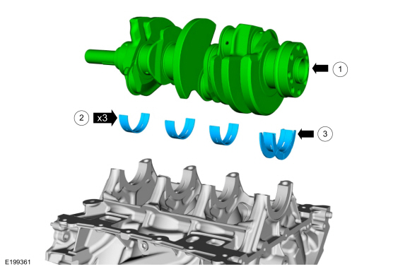
Remove and discard the main bearing cap bolts.
-
-
Remove the main bearing caps.
-
Remove the lower thrust washer.
-
Remove the lower main bearings.
-
-
Remove the crankshaft.
-
Remove the lower main bearings.
-
Remove the lower thrust bearing.
-
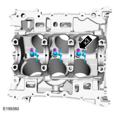
Remove the bolts and the piston cooling jets from the cylinder block.
Special Tool(s) /
General Equipment
205-153
(T80T-4000-W)
Handle
303-1246Engine Spreader BarTKIT-2006UF-FLMTKIT-2006UF-ROW
303-1247VCT Spark Plug Tube Seal Remover and InstallerTKIT-2006UF-FLMTKIT-2006UF-ROW
303-1634Lift Eyes (2)TKIT-2014D-ROW3TKIT-2014D-FL_ROW
303-409
(T92C-6700-CH)
Remover, Crankshaft SealTKIT-1992-FH/FMH/FLMHTKIT-1993-LMH/MH
Floor Crane
Mounting Stand
Plastic Scraper
Flat-Bladed Screwdriver
Materials
Name
Specification
Motorcraft® Silicone Gasket RemoverZC-30-A
-
Motorcraft® Metal Surface Prep WipesZC-31-B
-
Motorcraft® Metal Brake Parts CleanerPM-4-A, PM-4-B
-
NOTICE:
During engine repair procedures, cleanliness is extremely
important...
Special Tool(s) /
General Equipment
303-1249Valve Spring CompressorTKIT-2006UF-FLMTKIT-2006UF-ROW
303-1418Compressor, Valve SpringTKIT-2008ET-FLMTKIT-2008ET-ROW
303-1567Sizer, Teflon SealTKIT-2010C-FLM
303-300
(T87C-6565-A)
Set, Valve Spring CompressorTKIT-1988-FESTIVAT88C-1000-STTKIT-1988-TRACERTKIT-2009TC-F
303-350
(T89P-6565-A)
Compressor, Valve SpringTKIT-1990-LMHTKIT-1989-FTKIT-1989-FMTKIT-1989-FLM
307-005
(T59L-100-B)
Slide Hammer
310-205Fuel Injector Brush
310-206Remover, Fuel InjectorTKIT-2009A-FLM
310-207Installer, Fuel Injector Seal AssemblyTKIT-2009A-FLM
DISASSEMBLY
NOTICE:
During engine repair procedures, cleanliness is extremely
important...
Other information:
System Operation
System Diagram - Exterior, Power, Without Memory
Item
Description
1
Exterior mirror control switch
2
LH front door window control switch
3
LIN
4
MS-CAN
5
DDM
6
PDM
7
LH exterior mirror
8
RH exterior mirror
Network Message Chart
Module Network Input Messages — PDM
Broadcast Message
Originating Module
Message Purpose
Passenger mirror command
DDM
Contains the movement requests for the RH exterior mirror glass generated by the exterior mirror control switch...
This feature shuts down the engine if it has
been idling for an extended period. The
ignition also turns off in order to save battery
power. Before your vehicle shuts down, a
message appears in the information display
showing a timer counting down from 30
seconds...
.jpg)
.jpg)
.jpg)
.jpg)
.jpg)
.jpg)
.jpg)
.jpg)
.jpg)
.jpg)
.jpg)
.jpg)
.jpg)
.jpg)
.jpg)
.jpg)
.jpg)
.jpg)
.jpg)
.jpg)
.jpg)
.jpg)
.jpg)
.jpg)
.jpg)
.jpg)
.jpg)
.jpg)
.jpg)
.jpg)
.jpg)
.jpg)
.jpg)
.jpg)
.jpg)
.jpg)
.jpg)
.jpg)
.jpg)
.jpg)
.jpg)
.jpg)
.jpg)
.jpg)
.jpg)
.jpg)
.jpg)
.jpg)
.jpg)
.jpg)
.jpg)
.jpg)
.jpg)
.jpg)
.jpg)
.jpg)
.jpg)
.jpg)
.jpg)
.jpg)
.jpg)
.jpg)
.jpg)
.jpg)
.jpg)
.jpg)
.jpg)
.jpg)
.jpg)
.jpg)
.jpg)
.jpg)
.jpg)
.jpg)
.jpg)
.jpg)
.jpg)
.jpg)
.jpg)
.jpg)
.jpg)
.jpg)
.jpg)
.jpg)
.jpg)
.jpg)
 Removal - Engine Block Skirt Stiffener
 Disassembly and Assembly of Subassemblies - Cylinder Head