Lincoln Aviator: High Voltage Battery / General Information
WARNING: This battery pack should only be serviced by an authorized electric vehicle technician. Improper handling can result in personal injury or death.
WARNING: Apply the parking brake, shift into park (P), switch the ignition off and remove the key before you open the hood or have any service or repair work completed. If you do not switch the ignition off, the engine could restart at any time. Failure to follow this instruction could result in personal injury or death.
WARNING: Do not touch the electronic ignition system parts after you have switched the ignition on or when the engine is running. The system operates at high voltage. Failure to adhere to this warning could result in serious personal injury or death.
WARNING: Keep your hands and clothing clear of the engine cooling fan. Your vehicle consists of various high-voltage components and wiring. All of the high-voltage power flows through specific wiring assemblies labeled as such or covered with a solid orange convolute, or orange striped tape, or both. Do not come in contact with these components.
The high-voltage battery system is a high-voltage, lithium-ion battery system. The pack is located underneath the vehicle. The high voltage battery system uses an advanced active liquid heating and cooling system to regulate high voltage battery temperature and help maximize the life of the high voltage battery.
Note: The high-voltage battery does not require regular service maintenance.
 Charging the High Voltage Battery - Plug-In Hybrid Electric Vehicle (PHEV)
IMPORTANT SAFETY INSTRUCTIONS
WARNING: In Canada, do not use
the 120 volt convenience cord in
commercial garages.
WARNING: This equipment has
arcing or sparking parts...
Other information:
Lincoln Aviator 2020-2026 Service Manual: Diagnosis and Testing - Parking, Rear and License Plate Lamps
Diagnostic Trouble Code (DTC) Chart Diagnostics in this manual assume a certain skill level and knowledge of Ford-specific diagnostic practices. REFER to: Diagnostic Methods (100-00 General Information, Description and Operation). Diagnostic Trouble Code Chart Module DTC Description Action BCM B10F3:11 Left Front Position Light:Circuit Short to Ground GO to Pinpoint Test D BCM B10F3:15 Left Front Position Light:Circuit Short to Battery or Open GO to Pinpoint Test D BCM B10F4:11 Right Front Position Light:Circuit Short to Ground GO to Pinpoint Test D BCM B10F4:15 Right Front Position Light:Circuit Short to Battery or Open GO to Pinpoint Test D BCM B1445:11 Rear Park Lamps Output:Circuit Short to Ground GO to Pinpoint Test D BCM B1445:15 Rear Park Lamps Output:Circuit Short to Battery or Open GO to Pinpoint Test D BCM B149E:11 Left Front Position/Sidemarker:Circuit Short To Ground GO to Pinpoint Test D BCM B149E:15 Left Front Position/Sidemarker:Circuit Short To Battery or Open GO to Pinpoint Test D BCM B149F:11 Right Front Position/Sidemarker:Circuit Short To Ground GO to Pinpoint Test D BCM B149F:15 Right Front Position/Sidemarker:Circuit Short To Battery or Open GO to Pinpoint Test D BCM B14A2:11 Tailgate/Liftgate Applique Lamps:Circuit Short To Ground GO to Pinpoint Test D BCM B14A2:15 Tailgate/Liftgate Applique Lamps:Circuit Short To Battery or Open GO to Pinpoint Test D BCM B14B2:11 Left Position Lamps:Circuit Short To Ground GO to Pinpoint Test D BCM B14B2:15 Left Position Lamps:Circuit Short To Battery or Open GO to Pinpoint Test D BCM B14B3:11 Right Position Lamps:Circuit Short To Ground GO to Pinpoint Test D BCM B14B3:15 Right Position Lamps:Circuit Short To Battery or Open GO to Pinpoint Test D BCM B14E4:01 Extra Enhanced Exterior Lighting System:General Electrical Failure GO to Pinpoint Test E BCM B14E4:08 Extra Enhanced Exterior Lighting System:Bus Signal / Message Failure GO to Pinpoint Test E BCM B14E4:1C Extra Enhanced Exterior Lighting System:Circuit Voltage Out of Range GO to Pinpoint Test E BCM B14E4:49 Extra Enhanced Exterior Lighting System:Internal Electronic Failure GO to Pinpoint Test E BCM B14E4:55 Extra Enhanced Exterior Lighting System:Not Configured GO to Pinpoint Test E BCM B14E4:61 Extra Enhanced Exterior Lighting System:Signal Calculation Failure GO to Pinpoint Test E Symptom Charts Symptom Chart: Parking, Rear and License Plate Lamps Diagnostics in this manual assume a certain skill level and knowledge of Ford-specific diagnostic practices...
Lincoln Aviator 2020-2026 Service Manual: Description and Operation - Direct Current/Direct Current (DC/DC) Converter Control Module - System Operation and Component Description
System Operation System Diagram - DCDC Item Description 1 Ignition Switch 2 PCM 3 SOBDMC 4 BCM 5 BECM 6 DCDC 7 High Voltage/Low Current Fuse 8 12V Battery Monitoring Sensor Network Message Chart DCDC Network Input Messages Broadcast Message Originating Module Message Purpose DCDC HEV wake up enable BECM, BCCM (battery charger control module) ( PHEV only) Command to enable the DCDC DCDC HEV wake up enable SOBDMC Hard wired command to enable the DCDC High voltage input SOBDMC Voltage measured at SOBDMC used to compare with voltage at the DCDC...
Categories
- Manuals Home
- Lincoln Aviator Owners Manual
- Lincoln Aviator Service Manual
- Description and Operation - Jacking and Lifting
- Opening and Closing the Hood
- Tire Change Procedure
- New on site
- Most important about car
Remote Control
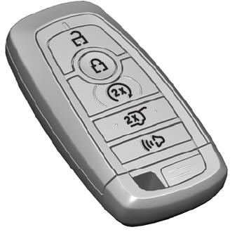
Passive Key

The passive key operates the power locks and the remote start system. The passive key must be in your vehicle to use the push button start.
Note: You may not be able to shift out of park (P) unless the passive key is inside your vehicle.

