Lincoln Aviator: Parking Aid - Vehicles With: Parking Aid Camera / General Procedures - Parking Aid Camera Initialization

  1. Using a scan tool select the controlling module for the parking aid camera(s).
  1. Carry out the LIN new module initialization.
  1. Follow the on-screen instructions.
  1. Check the vehicle for the active guidelines option. Refer to description and operation in the appropriate vehicle section.
  1. If equipped with active guidelines, drive the vehicle on a flat, smooth road at 32 km/h (20 mph) or more, with hands placed loosely on the steering wheel and minimal steering correction for approximately 30 seconds.

    NOTE: When the battery has been disconnected or discharged the active guidelines may be inoperative until the following step is carried out.

    General Procedures - 360 Degree View Camera Alignment

    NOTE: On vehicles equipped with Trailer Reverse Guidance (TRG) this procedure also perform the Trailer Reverse Guidance camera alignment. NOTE: Damage to or misalignment of any of the cameras or the body panels they are mounted to can cause the camera alignment to be unsuccessful...

    Removal and Installation - Front Parking Aid Camera

    Removal Remove the front bumper cover. Refer to: Front Bumper Cover (501-19 Bumpers, Removal and Installation). Disconnect the front camera coaxial cable connector and the front camera washer hose...

    Other information:

    Lincoln Aviator 2020-2025 Service Manual: Removal and Installation - Shock Absorber and Spring Assembly


    Removal NOTICE: Suspension fasteners are critical parts that affect the performance of vital components and systems. Failure of these fasteners may result in major service expense. Use the same or equivalent parts if replacement is necessary. Do not use a replacement part of lesser quality or substitute design...

    Lincoln Aviator 2020-2025 Service Manual: Diagnosis and Testing - Passive Anti-Theft System (PATS)


    Diagnostic Trouble Code (DTC) Chart Diagnostics in this manual assume a certain skill level and knowledge of Ford-specific diagnostic practices. REFER to: Diagnostic Methods (100-00 General Information, Description and Operation).   Diagnostic Trouble Code Chart Module   DTC Description Action   BCM B1551:51 Phone As A Key: Not Programmed   GO to Pinpoint Test G   BCM B155E:00 Incorrect Response from Immobilizer SubControl Module: No Sub Type Information   GO to Pinpoint Test M   RFA B1589:29 Antenna #3: Signal Invalid   GO to Pinpoint Test A   RFA B1589:31 Antenna #3: No Signal   GO to Pinpoint Test A   RFA B1589:45 Antenna #3: Program Memory Failure   GO to Pinpoint Test A   RFA B1589:49 Antenna #3: Internal Electronic Failure   GO to Pinpoint Test A   RFA B1589:57 Antenna #3: Invalid/ Incompatible Software Component   GO to Pinpoint Test A   RFA B1590:29 Antenna #4: Signal Invalid   GO to Pinpoint Test A   RFA B1590:31 Antenna #4: No Signal   GO to Pinpoint Test A   RFA B1590:45 Antenna #4: Program Memory Failure   GO to Pinpoint Test A   RFA B1590:49 Antenna #4: Internal Electronic Failure   GO to Pinpoint Test A   RFA B1590:57 Antenna #4: Invalid/ Incompatible Software Component   GO to Pinpoint Test A   RFA B1591:29 Antenna #5: Signal Invalid   GO to Pinpoint Test B   RFA B1591:31 Antenna #5: No Signal   GO to Pinpoint Test B   RFA B1591:45 Antenna #5: Program Memory Failure   GO to Pinpoint Test B   RFA B1591:49 Antenna #5: Internal Electronic Failure   GO to Pinpoint Test B   RFA B1591:57 Antenna #5: Invalid/ Incompatible Software Component   GO to Pinpoint Test B   RFA B1592:29 Antenna #6: Signal Invalid   GO to Pinpoint Test B   RFA B1592:31 Antenna #6: No Signal   GO to Pinpoint Test B   RFA B1592:45 Antenna #6: Program Memory Failure   GO to Pinpoint Test B   RFA B1592:49 Antenna #6: Internal Electronic Failure   GO to Pinpoint Test B   RFA B1592:57 Antenna #6: Invalid/ Incompatible Software Component   GO to Pinpoint Test B   RFA B1593:29 Antenna #7: Signal Invalid   GO to Pinpoint Test C   RFA B1593:31 Antenna #7: No Signal   GO to Pinpoint Test C   RFA B1593:45 Antenna #7: Program Memory Failure   GO to Pinpoint Test C   RFA B1593:49 Antenna #7: Internal Electronic Failure   GO to Pinpoint Test C   RFA B1593:57 Antenna #7: Invalid/ Incompatible Software Component   GO to Pinpoint Test C   RFA B1594:29 Antenna #8: Signal Invalid   GO to Pinpoint Test B   RFA B1594:31 Antenna #8: No Signal   GO to Pinpoint Test B   RFA B1594:45 Antenna #8: Program Memory Failure   GO to Pinpoint Test B   RFA B1594:49 Antenna #8: Internal Electronic Failure   GO to Pinpoint Test B   RFA B1594:57 Antenna #8: Invalid/ Incompatible Software Component   GO to Pinpoint Test B   RFA B1595:29 Antenna #9: Signal Invalid   GO to Pinpoint Test C   RFA B1595:31 Antenna #9: No Signal   GO to Pinpoint Test C   RFA B1595:45 Antenna #9: Program Memory Failure   GO to Pinpoint Test C   RFA B1595:49 Antenna #9: Internal Electronic Failure   GO to Pinpoint Test C   RFA B1595:57 Antenna #9: Invalid/ Incompatible Software Component   GO to Pinpoint Test C   RFA B1596:29 Antenna #10: Signal Invalid   GO to Pinpoint Test C   RFA B1596:31 Antenna #10: No Signal   GO to Pinpoint Test C   RFA B1596:45 Antenna #10: Program Memory Failure   GO to Pinpoint Test C   RFA B1596:49 Antenna #10: Internal Electronic Failure   GO to Pinpoint Test C   RFA B1596:57 Antenna #10: Invalid/ Incompatible Software Component   GO to Pinpoint Test C   RFA B1597:29 Antenna #11: Signal Invalid   GO to Pinpoint Test D   RFA B1597:31 Antenna #11: No Signal   GO to Pinpoint Test D   RFA B1597:45 Antenna #11: Program Memory Failure   GO to Pinpoint Test D   RFA B1597:49 Antenna #11: Internal Electronic Failure   GO to Pinpoint Test D   RFA B1597:57 Antenna #11: Invalid/ Incompatible Software Component   GO to Pinpoint Test D   RFA B15A5:56 Bluetooth Low Energy Module: Invalid/ Incompatible Configuration   GO to Pinpoint Test E   RFA B1A56:29 Antenna: Signal Invalid   GO to Pinpoint Test A   RFA B1A56:31 Antenna: No Signal   GO to Pinpoint Test A   RFA B1A56:45 Antenna: Program Memory Failure   GO to Pinpoint Test A   RFA B1A56:49 Antenna: Internal Electronic Failure   GO to Pinpoint Test A   RFA B1A56:57 Antenna: Invalid/ Incompatible Software Component   GO to Pinpoint Test A   RFA B1D55:29 Antenna #2: Signal Invalid   GO to Pinpoint Test D   RFA B1D55:31 Antenna #2: No Signal   GO to Pinpoint Test D   RFA B1D55:45 Antenna #2: Program Memory Failure   GO to Pinpoint Test D   RFA B1D55:49 Antenna #2: Internal Electronic Failure   GO to Pinpoint Test D   RFA B1D55:57 Antenna #2: Invalid/ Incompatible Software Component   GO to Pinpoint Test D   RFA P0601:41 Internal Control Module Memory Checksum Error: General Checksum Failure   GO to Pinpoint Test K   RFA P1269:00 Immobilizer Code Not Programmed: No Sub Type Information   GO to Pinpoint Test G   RFA P1602:00 Immobilizer/ ECM Communication Error: No Sub Type Information   GO to Pinpoint Test G   RFA P1622:00 Immobilizer ID Does Not Match: No Sub Type Information   GO to Pinpoint Test G   RFA P1623:00 Immobilizer Code Word/ID Number Write Failure: No Sub Type Information   GO to Pinpoint Test G   RFA U0146:08 Lost Communication With Gateway "A": Bus Signal/Message Failure   GO to Pinpoint Test L   RFA U0198:00 Lost Communication With Telematic Control Module: No Sub Type Information   GO to Pinpoint Test L   RFA U0422:00 Invalid Data Received From Body Control Module: No Sub Type Information   GO to Pinpoint Test G   RFA U200D:11 Control Module Output Power A: Circuit Short to Ground   GO to Pinpoint Test A   RFA U200D:15 Control Module Output Power A: Circuit Short to Battery or Open   GO to Pinpoint Test A   RFA U200E:11 Control Module Output Power B: Circuit Short to Ground   GO to Pinpoint Test B   RFA U200E:15 Control Module Output Power B: Circuit Short to Battery or Open   GO to Pinpoint Test B   RFA U200F:11 Control Module Output Power C: Circuit Short to Ground   GO to Pinpoint Test C   RFA U200F:15 Control Module Output Power C: Circuit Short to Battery or Open   GO to Pinpoint Test C   RFA U201A:06 Control Module Main Calibration Data: Algorithm Based Failure   GO to Pinpoint Test F   RFA U201A:46 Control Module Main Calibration Data: Calibration/ Parameter Memory failure   GO to Pinpoint Test F   RFA U201A:55 Control Module Main Calibration Data: Not Configured   GO to Pinpoint Test F   RFA U2100:55 Initial Configuration Not Complete: Not Configured   GO to Pinpoint Test F   RFA U3000:42 Control Module: General Memory Failure   GO to Pinpoint Test K   RFA U3000:44 Control Module: Data Memory Failure   GO to Pinpoint Test K   RFA U3000:49 Control Module: Internal Electronic Failure   GO to Pinpoint Test K   RFA U3003:16 Battery Voltage: Circuit Voltage Below Threshold   GO to Pinpoint Test I   RFA U3003:17 Battery Voltage: Circuit Voltage Above Threshold   GO to Pinpoint Test J Symptom Chart Symptom Chart: PATS Diagnostics in this manual assume a certain skill level and knowledge of Ford-specific diagnostic practices...

    Categories

    Activating Intelligent Access

    The intelligent access key must be within 3 ft (1 m) of the door or luggage compartment you intend to lock or unlock.

    At a Door

    Electronic door handles are on each door. Gently depress the switch inside the exterior door handle to unlock and open the door. An unlock symbol illuminates on the door window trim indicating your vehicle is unlocked.
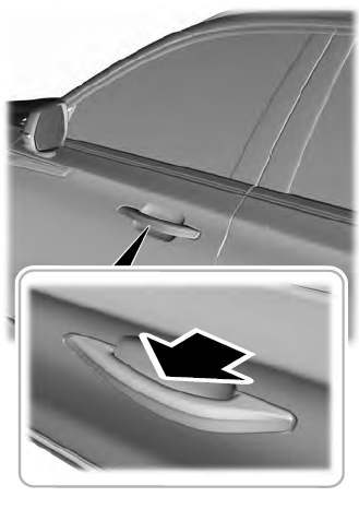
    Lincoln Aviator. Activating Intelligent Access

    read more

     
    Copyright © 2025 www.liaviator2.com