Lincoln Aviator 2020-2026 Service Manual / Electrical / Instrumentation and Warning Systems / Parking Aid - Vehicles With: Parking Aid Camera / General Procedures - 360 Degree View Camera Alignment
Lincoln Aviator: Parking Aid - Vehicles With: Parking Aid Camera / General Procedures - 360 Degree View Camera Alignment
NOTE: On vehicles equipped with Trailer Reverse Guidance (TRG) this procedure also perform the Trailer Reverse Guidance camera alignment.
NOTE: Damage to or misalignment of any of the cameras or the body panels they are mounted to can cause the camera alignment to be unsuccessful.
-
Prior to beginning this procedure, perform the following:
-
Verify the exterior rear view mirrors to make sure they are in normal driving position.
-
Verify suspension is in a normal driving mode if equipped with adjustable suspension.
-
Verify that all doors, deck lid, liftgate and tailgate are closed.
-
Using a scan tool retrieve and if necessary repair any parking aid camera Diagnostic Trouble Codes (DTCs).
-
Clean the camera lenses. Inspect all cameras (except
center high-mounted stoplamp camera and trailer camera, if equipped),
the associated mounting hardware and body components for damage.
-
Verify the exterior rear view mirrors to make sure they are in normal driving position.
-
Environmental conditions that may affect the procedure:
-
Perform procedure in day light.
-
Perform procedure when visibility is clear with high
contrast scenes that are not disturbed by strong rainfall or snow.
-
Recommend driving on normal asphalt or concrete road surface.
-
Avoid road surfaces that have a smooth and uniform appearance (e.g. snow blanketed roadway).
-
Perform procedure in day light.
-
Using a scan tool carry out the 360 Degree view camera alignment procedure.
NOTE: The vehicle needs to be driven for approximately 5 to 10 minutes or possibly longer depending on the environmental conditions.
.jpg) |
-
Follow the on-screen instructions.
-
After the procedure is successful, verify the quality of the
360 degree view camera on the display. If necessary, repeat the
procedure to achieve the best 360 view image results.
-
Drive to a parking lot and stop vehicle over straight parking designation lines.
-
Activate the 360 degree view camera system.
-
Drive slowly over the parking designation lines while
watching the corners of the 360 image for stitching quality. Lines
should look continuous.
-
Drive to a parking lot and stop vehicle over straight parking designation lines.
 Diagnosis and Testing - Parking Aid
Diagnostic Trouble Code (DTC) Chart
Diagnostics in this manual assume a certain skill level and knowledge of Ford-specific diagnostic practices. REFER to: Diagnostic Methods (100-00 General Information, Description and Operation)...
 General Procedures - Parking Aid Camera Initialization
Using a scan tool select the controlling module for the parking aid camera(s).
Carry out the LIN new module initialization...
Other information:
Lincoln Aviator 2020-2026 Service Manual: General Procedures - Air Conditioning (A/C) System Recovery, Evacuation and Charging - Vehicles With: R134A Refrigerant
Special Tool(s) / General Equipment Air Conditioning Service Unit Refrigerant Identification Equipment Recovery NOTICE: Use an A/C refrigerant analyzer before recovering any of the vehicle's A/C refrigerant. Failure to do so puts the shop's bulk refrigerant at risk of contamination...
Lincoln Aviator 2020-2026 Service Manual: Removal and Installation - Engine Front Cover
Special Tool(s) / General Equipment 303-050 (T70P-6000) Lifting Bracket, Engine 303-F070Support Bar, EngineTKIT-1999A-F/LTTKIT-1999A-FM/FLM Plastic Scraper Hose Clamp Remover/Installer Flat-Bladed Screwdriver Materials Name Specification Motorcraft® High Performance Engine RTV SiliconeTA-357 WSE-M4G323-A6 Motorcraft® Metal Brake Parts CleanerPM-4-A, PM-4-B - Removal NOTICE: During engine repair procedures, cleanliness is extremely important...
Categories
- Manuals Home
- Lincoln Aviator Owners Manual
- Lincoln Aviator Service Manual
- Keyless Entry
- Wireless Accessory Charger (If Equipped)
- Fuel Quality
- New on site
- Most important about car
Fastening the Seatbelts
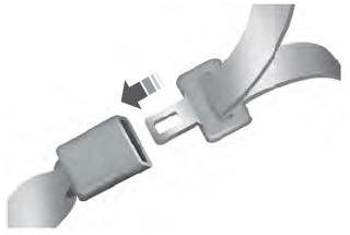
The front outboard and rear safety restraints in the vehicle are combination lap and shoulder belts.
Insert the belt tongue into the proper buckle (the buckle closest to the direction the tongue is coming from) until you hear a snap and feel it latch. Make sure that you securely fasten the tongue in the buckle.
Copyright © 2026 www.liaviator2.com
