
Lincoln Aviator 2020-2026 Service Manual / Electrical / Instrumentation and Warning Systems / Parking Aid - Vehicles With: Rear Parking Aid / General Procedures - Azimuth System Check
Lincoln Aviator: Parking Aid - Vehicles With: Rear Parking Aid / General Procedures - Azimuth System Check
Check
-
NOTE: The object used in this system check can be fabricated using a 9 cm diameter (3 in I.D.) pipe, 100 cm (39 in) in length (available as Polyvinyl Chloride (PVC) pipe, or similar from a hardware or plumbing supply.
NOTE: The following system check should be carried out with the vehicle on a level surface.
NOTE: Actual sensor arrangement may differ from the configuration shown.
Distribute the test objects evenly across the bumper as shown. Refer to the specifications in this section.
.jpg) |
-
Turn the ignition switch to the ON position, engine off.
-
Apply the parking brake.
-
Select REVERSE (R) for rear parking aid.
-
Select DRIVE (D) for front parking aid.
-
NOTE: The system provides audio warnings only when the vehicle is moving or when the vehicle is stationary and the detected obstacle is less than 12 in (30 cm) away from the bumper.
Using a diagnostic scan tool, monitor the parking aid sensor distance Parameter Identifications (PIDs) to verify the objects are detected when placed in the specified locations (P1, P2, P3, P4 and P5).
 Diagnosis and Testing - Parking Aid
Diagnostic Trouble Code (DTC) Chart
Diagnostics in this manual assume a certain skill level and knowledge of Ford-specific diagnostic practices. REFER to: Diagnostic Methods (100-00 General Information, Description and Operation)...
 General Procedures - Elevation System Check
Check
Turn the ignition ON, engine OFF.
Set the parking brake.
Place the gearshift in REVERSE (R) for rear parking aid sensors...
Other information:
Lincoln Aviator 2020-2026 Service Manual: General Procedures - High Voltage System De-energizing
Depower WARNING: To prevent the risk of high-voltage shock, always follow precisely all warnings and service instructions, including instructions to depower the system. The high-voltage system utilizes approximately 450 volts DC, provided through high-voltage cables to its components and modules...
Lincoln Aviator 2020-2026 Owners Manual: Heated Steering Wheel (If equipped)
The heated steering wheel button is on the climate controls. Press the button to switch the heated steering wheel on and off. Note: You can use the heated steering wheel only when the engine is running. Note: The system uses a sensor and is designed to control the temperature of the steering wheel and to prevent it from overheating...
Categories
- Manuals Home
- Lincoln Aviator Owners Manual
- Lincoln Aviator Service Manual
- Child Safety Locks
- Remove and Reinstall the Battery
- Interior Lamps
- New on site
- Most important about car
Fastening the Seatbelts
The front outboard and rear safety restraints in the vehicle are combination lap and shoulder belts.
Insert the belt tongue into the proper buckle (the buckle closest to the direction the tongue is coming from) until you hear a snap and feel it latch. Make sure that you securely fasten the tongue in the buckle.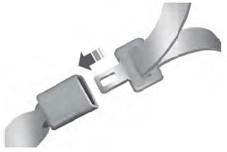

Copyright © 2026 www.liaviator2.com