Lincoln Aviator: General Information / Description and Operation - High Voltage System Health and Safety Precautions - Overview
.jpg) WARNING:
Service of the high voltage system on this vehicle is
restricted to qualified personnel. The required qualifications vary by
region. Always observe local laws and legislative directives regarding
electric vehicle service. Failure to follow this instruction may result
in serious personal injury or death.
WARNING:
Service of the high voltage system on this vehicle is
restricted to qualified personnel. The required qualifications vary by
region. Always observe local laws and legislative directives regarding
electric vehicle service. Failure to follow this instruction may result
in serious personal injury or death.
.jpg) WARNING:
To prevent the risk of high-voltage shock, always follow
precisely all warnings and service instructions including instructions
to depower the system. The high-voltage system utilizes approximately
300
V DC, provided through high-voltage cables to its
components and modules. The high-voltage cables and wiring are
identified by orange harness tape or orange wire covering. All
high-voltage components are marked with high-voltage warning labels with
a high-voltage symbol. Failure to follow these instructions may result
in serious personal injury or death.
WARNING:
To prevent the risk of high-voltage shock, always follow
precisely all warnings and service instructions including instructions
to depower the system. The high-voltage system utilizes approximately
300
V DC, provided through high-voltage cables to its
components and modules. The high-voltage cables and wiring are
identified by orange harness tape or orange wire covering. All
high-voltage components are marked with high-voltage warning labels with
a high-voltage symbol. Failure to follow these instructions may result
in serious personal injury or death.
.jpg) WARNING:
Never install the service disconnect plug when a
high-voltage service cover is removed. Always install the cover prior to
connecting the service disconnect plug. The cover prevents inadvertent
contact with the high voltage which is present at several points under
the cover. Failure to follow these instructions may result in serious
personal injury or death.
WARNING:
Never install the service disconnect plug when a
high-voltage service cover is removed. Always install the cover prior to
connecting the service disconnect plug. The cover prevents inadvertent
contact with the high voltage which is present at several points under
the cover. Failure to follow these instructions may result in serious
personal injury or death.
.jpg) WARNING:
Disconnect the
12
V battery before servicing the direct current to
alternating current (DC-AC) inverter or alternating current (AC)
powerpoint to prevent the risk of high voltage shock. Failure to follow
this instruction may result in serious personal injury.
WARNING:
Disconnect the
12
V battery before servicing the direct current to
alternating current (DC-AC) inverter or alternating current (AC)
powerpoint to prevent the risk of high voltage shock. Failure to follow
this instruction may result in serious personal injury.
.jpg) WARNING:
Extreme heat such as paint drying ovens will cause the
damage of the high voltage battery. The high voltage battery must be
removed before using paint drying ovens longer than 45 minutes or with
temperatures above 60°C (140°F). Failure to follow this instruction may
result in damaging the high voltage battery, which could cause serious
personal injury or death in a fire or explosion.
WARNING:
Extreme heat such as paint drying ovens will cause the
damage of the high voltage battery. The high voltage battery must be
removed before using paint drying ovens longer than 45 minutes or with
temperatures above 60°C (140°F). Failure to follow this instruction may
result in damaging the high voltage battery, which could cause serious
personal injury or death in a fire or explosion.
 Description and Operation - Health and Safety Precautions
General Service Warnings
Review carefully the information below before beginning
any repair. Following these warnings is a list of specific system
warnings that must be reviewed before beginning work on any listed
system...
 Description and Operation - Pyrotechnic Device Health and Safety Precautions
WARNING:
Service and handling of Pyrotechnic Components is restricted to
qualified personnel. The required qualifications vary by region. Always
observe local laws and legislative directives regarding Pyrotechnic
Components service and handling...
Other information:
Lincoln Aviator 2020-2025 Service Manual: Removal and Installation - Front Door Moulding
Removal NOTE: Removal steps in this procedure may contain installation details. NOTE: LH door shown, RH door similar. NOTE: Do not use excessive force when removing retainers, to avoid damage to moulding. Using a non-marring trim tool, disengage the retainers attaching moulding to the door...
Lincoln Aviator 2020-2025 Service Manual: General Procedures - Crankshaft Main Bearing Journal Clearance
Check NOTE: Refer to the appropriate Section 303-01 for the specification. NOTE: Crankshaft main bearing journals must be within specifications before checking journal clearance. Remove the crankshaft main bearing cap and crankshaft main bearing...
Categories
- Manuals Home
- Lincoln Aviator Owners Manual
- Lincoln Aviator Service Manual
- Anti-Theft Alarm
- Opening and Closing the Hood
- Configuring The Head Up Display
- New on site
- Most important about car
Fastening the Seatbelts
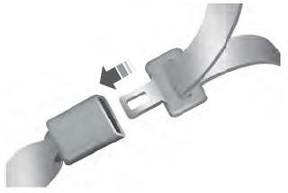
The front outboard and rear safety restraints in the vehicle are combination lap and shoulder belts.
Insert the belt tongue into the proper buckle (the buckle closest to the direction the tongue is coming from) until you hear a snap and feel it latch. Make sure that you securely fasten the tongue in the buckle.
