Lincoln Aviator 2020-2024 Service Manual / Chassis / Brake System / Brake System - General Information / General Procedures - Brake Service Mode Activation and Deactivation

Lincoln Aviator: Brake System - General Information / General Procedures - Brake Service Mode Activation and Deactivation

Activation

  WARNING: Service actions on vehicles equipped with electronic parking brakes may cause unexpected parking brake application, which could result in injury to hands or fingers. Put the electronic parking brake system into service mode prior to servicing or removing rear brake components. Failure to follow this instruction may result in serious personal injury.

  WARNING: Service actions on vehicles equipped with electronic brake booster without activating the brake system service mode may result in unexpected hydraulic brake application or a false leak detection DTC. This will significantly reduce the performance of the brake system. Failure to follow this instruction may result in serious personal injury.

NOTE: Brake service mode is also known as brake maintenance mode.

NOTE: Prior to carrying out the brake service mode activation steps below, clear all EPB and EBB related DTC's.

NOTE: Carry out the following service mode activation procedure to deactivate the EPB and EBB systems. The EPB and EBB system can also be deactivated using the diagnostic scan tool and following the on-screen instructions.

NOTE: This mode is required to deactivate the brake boost and to allow the entire brake system to be bleed manually.

NOTE: This mode will cause all the associated brake warning indicators and text messages to appear.

  1. Set the ignition to ON.
  1. Release the EPB.
  1. Press and hold the accelerator pedal and place the EPB switch to the RELEASE (downward) position. Continue to hold the accelerator pedal and EPB switch.
  1. Set the ignition to OFF then set the ignition to ON within 5 seconds. Continue to hold the accelerator pedal and the EPB switch.
  1. Set the ignition to OFF then release the accelerator pedal and EPB switch.
    • NOTE: The brake system will be deactivated, preventing brake application until service has been completed and service mode has been deactivated. The yellow EPB indicator will be illuminated and Maintenance Mode will display on the message center.

    • NOTE: When replacing brake pads in service mode, the brake caliper piston must be compressed into the caliper housing. The brake caliper piston does not have to be rotated while compressing the piston.

Deactivation

NOTICE: The brake system performance will be significantly reduced when the brake system is put in service mode.

NOTE: Carry out the following Brake Maintenance Mode deactivation procedure to activate the EBB and EPB systems. These systems can also be activated using the diagnostic scan tool and following the on-screen instructions.

  1. Set the ignition to ON.
  1. Press and hold the accelerator pedal.
  1. Place the EPB switch in the APPLY (upward) position. Continue to hold the accelerator pedal and the EPB switch.
  1. Firmly press the brake pedal for at least 1 second. Release the brake pedal while continuing to hold the accelerator pedal and the EPB switch.
  1. Set the ignition to OFF then set the ignition to ON within 5 seconds, then release the accelerator pedal and the EPB switch.
    • NOTE: Once the ignition is set to ON, the EPB system will immediately apply and release the parking brake to guarantee sufficient air gap between the rear brake pads and brake disc. If the EPB switch is not released prior to completion of this sequence, it will apply the EPB. The EPB will have to released prior to moving the vehicle.

    • NOTE: When Brake Maintenance Mode is deactivated, the Yellow Parking Brake and Red Brake Warning Indicators turn off and "Brake Maintenance Mode" no longer displays in the message center.

    General Procedures - Brake Disc Machining

    Repair NOTE: On-Vehicle Brake Lathe Training Videos Vehicle preparation.    Click here to view a video version of this procedure...

    General Procedures - Brake System Draining and Filling

    D..

    Other information:

    Lincoln Aviator 2020-2024 Service Manual: Diagnosis and Testing - Vehicle Dynamic Suspension - Vehicles With: Air Suspension


    Diagnostic Trouble Code (DTC) Chart Diagnostics in this manual assume a certain skill level and knowledge of Ford-specific diagnostic practices. REFER to: Diagnostic Methods (100-00 General Information, Description and Operation).   Diagnostic Trouble Code Chart Module   DTC Description Action   SUMA B1041:52 Levelling Control: Not Activated   GO to Pinpoint Test W   SUMA C1043:00 Pressure Decrease Too Slow From Reservoir: No Sub Type Information   GO to Pinpoint Test M   SUMA C104C:11 Left Rear Spring Rate Valve: Circuit Short To Ground   GO to Pinpoint Test E   SUMA C104C:12 Left Rear Spring Rate Valve: Circuit Short To Battery   GO to Pinpoint Test E   SUMA C104C:13 Left Rear Spring Rate Valve: Circuit Open   GO to Pinpoint Test E   SUMA C104C:1A Left Rear Spring Rate Valve: Circuit Resistance Below Threshold   GO to Pinpoint Test E   SUMA C104C:1F Left Rear Spring Rate Valve: Circuit Intermittent   GO to Pinpoint Test E   SUMA C104D:11 Right Front Spring Rate Valve: Circuit Short To Ground   GO to Pinpoint Test D   SUMA C104D:12 Right Front Spring Rate Valve: Circuit Short To Battery   GO to Pinpoint Test D   SUMA C104D:13 Right Front Spring Rate Valve: Circuit Open   GO to Pinpoint Test D   SUMA C104D:1A Right Front Spring Rate Valve: Circuit Resistance Below Threshold   GO to Pinpoint Test D   SUMA C104D:1F Right Front Spring Rate Valve: Circuit Intermittent   GO to Pinpoint Test D   SUMA C104E:11 Right Rear Spring Rate Valve: Circuit Short To Ground   GO to Pinpoint Test F   SUMA C104E:12 Right Rear Spring Rate Valve: Circuit Short To Battery   GO to Pinpoint Test F   SUMA C104E:13 Right Rear Spring Rate Valve: Circuit Open   GO to Pinpoint Test F   SUMA C104E:1A Right Rear Spring Rate Valve: Circuit Resistance Below Threshold   GO to Pinpoint Test F   SUMA C104E:1F Right Rear Spring Rate Valve: Circuit Intermittent   GO to Pinpoint Test F   SUMA C104F:11 Left Front Spring Rate Valve: Circuit Short To Ground   GO to Pinpoint Test C   SUMA C104F:12 Left Front Spring Rate Valve: Circuit Short To Battery   GO to Pinpoint Test C   SUMA C104F:13 Left Front Spring Rate Valve: Circuit Open   GO to Pinpoint Test C   SUMA C104F:1A Left Front Spring Rate Valve: Circuit Resistance Below Threshold   GO to Pinpoint Test C   SUMA C104F:1F Left Front Spring Rate Valve: Circuit Intermittent   GO to Pinpoint Test C   SUMA C1124:07 Height Sensor(s): Mechanical Failures   GO to Pinpoint Test G   SUMA C1124:11 Height Sensor(s): Circuit Short To Ground   GO to Pinpoint Test H   SUMA C1124:12 Height Sensor(s): Circuit Short To Battery   GO to Pinpoint Test H   SUMA C1124:54 Height Sensor(s): Missing Calibration   GO to Pinpoint Test U   SUMA C1A03:2A Left Front Height Sensor: Stuck in Range   GO to Pinpoint Test I   SUMA C1A03:34 Left Front Height Sensor: Signal High Time Less Than Minimum   GO to Pinpoint Test I   SUMA C1A03:35 Left Front Height Sensor: Signal High Time Greater Than Maximum   GO to Pinpoint Test I   SUMA C1A03:36 Left Front Height Sensor: Signal Frequency Too Low   GO to Pinpoint Test I   SUMA C1A03:37 Left Front Height Sensor: Signal Frequency Too High   GO to Pinpoint Test I   SUMA C1A03:84 Left Front Height Sensor: Signal Below Allowable Range   GO to Pinpoint Test I   SUMA C1A03:85 Left Front Height Sensor: Signal Above Allowable Range   GO to Pinpoint Test I   SUMA C1A04:2A Right Front Height Sensor: Stuck in Range   GO to Pinpoint Test J   SUMA C1A04:34 Right Front Height Sensor: Signal High Time Less Than Minimum   GO to Pinpoint Test J   SUMA C1A04:35 Right Front Height Sensor: Signal High Time Greater Than Maximum   GO to Pinpoint Test J   SUMA C1A04:36 Right Front Height Sensor: Signal Frequency Too Low   GO to Pinpoint Test J   SUMA C1A04:37 Right Front Height Sensor: Signal Frequency Too High   GO to Pinpoint Test J   SUMA C1A04:84 Right Front Height Sensor: Signal Below Allowable Range   GO to Pinpoint Test J   SUMA C1A04:85 Right Front Height Sensor: Signal Above Allowable Range   GO to Pinpoint Test J   SUMA C1A05:2A Left Rear Height Sensor: Stuck in Range   GO to Pinpoint Test K   SUMA C1A05:34 Left Rear Height Sensor: Signal High Time Less Than Minimum   GO to Pinpoint Test K   SUMA C1A05:35 Left Rear Height Sensor: Signal High Time Greater Than Maximum   GO to Pinpoint Test K   SUMA C1A05:36 Left Rear Height Sensor: Signal Frequency Too Low   GO to Pinpoint Test K   SUMA C1A05:37 Left Rear Height Sensor: Signal Frequency Too High   GO to Pinpoint Test K   SUMA C1A05:84 Left Rear Height Sensor: Signal Below Allowable Range   GO to Pinpoint Test K   SUMA C1A05:85 Left Rear Height Sensor: Signal Above Allowable Range   GO to Pinpoint Test K   SUMA C1A06:2A Right Rear Height Sensor: Stuck in Range   GO to Pinpoint Test L   SUMA C1A06:34 Right Rear Height Sensor: Signal High Time Less Than Minimum   GO to Pinpoint Test L   SUMA C1A06:35 Right Rear Height Sensor: Signal High Time Greater Than Maximum   GO to Pinpoint Test L   SUMA C1A06:36 Right Rear Height Sensor: Signal Frequency Too Low   GO to Pinpoint Test L   SUMA C1A06:37 Right Rear Height Sensor: Signal Frequency Too High   GO to Pinpoint Test L   SUMA C1A06:84 Right Rear Height Sensor: Signal Below Allowable Range   GO to Pinpoint Test L   SUMA C1A06:85 Right Rear Height Sensor: Signal Above Allowable Range   GO to Pinpoint Test L   SUMA C1A20:00 Pressure Increase Too Slow When Filling Reservoir: No Sub Type Information   GO to Pinpoint Test M   SUMA C1A27:09 Compressor: Component Failures   GO to Pinpoint Test N   SUMA C1A27:63 Compressor: Circuit/Component Protection Time-Out   GO to Pinpoint Test N   SUMA C1A27:98 Compressor: Component Or System Over Temperature   GO to Pinpoint Test N   SUMA C1A27:99 Compressor: Exceeded Learning Limit   GO to Pinpoint Test N   SUMA C1A31:63 Left Front Corner Valve: Circuit/Component Protection Time-Out   GO to Pinpoint Test AD   SUMA C1A32:63 Right Front Corner Valve: Circuit/Component Protection Time-Out   GO to Pinpoint Test AD   SUMA C1A33:63 Left Rear Corner Valve: Circuit/Component Protection Time-Out   GO to Pinpoint Test AD   SUMA C1A34:63 Right Rear Corner Valve: Circuit/Component Protection Time-Out   GO to Pinpoint Test AD   SUMA C1A36:63 Exhaust Valve: Circuit/Component Protection Time-Out   GO to Pinpoint Test AD   SUMA U0100:87 Lost Communication With ECM / PCM: Missing Message   GO to Pinpoint Test O   SUMA U0121:87 Lost Communication With Anti-Lock Brake System (ABS) Control Module: Missing Message   GO to Pinpoint Test P   SUMA U0122:87 Lost Communication With Vehicle Dynamics Control Module: Missing Message   GO to Pinpoint Test Q   SUMA U0131:87 Lost Communication With Power Steering Control Module "A": Missing Message   GO to Pinpoint Test R   SUMA U0140:87 Lost Communication With Body Control Module: Missing Message   GO to Pinpoint Test S   SUMA U0146:87 Lost Communication With Serial Data Gateway "A": Missing Message   GO to Pinpoint Test T   SUMA U0401:00 Invalid Data Received from ECM/PCM A: No Sub Type Information   GO to Pinpoint Test X   SUMA U0415:00 Invalid Data Received from Anti-Lock Brake System (ABS) Control Module "A": No Sub Type Information   GO to Pinpoint Test Y   SUMA U0416:00 Invalid Data Received From Vehicle Dynamics Control Module: No Sub Type Information   GO to Pinpoint Test Z   SUMA U0420:00 Invalid Data Received from Power Steering Control Module "A": No Sub Type Information   GO to Pinpoint Test AA   SUMA U0422:00 Invalid Data Received From Body Control Module: No Sub Type Information   GO to Pinpoint Test AB   SUMA U0447:00 Invalid Data Received From Serial Data Gateway "A": No Sub Type Information   GO to Pinpoint Test AC   SUMA U2100:00 Initial Configuration Not Complete: No Sub Type Information   GO to Pinpoint Test V   SUMA U2100:56 Initial Configuration Not Complete: Invalid/Incompatible Configuration   GO to Pinpoint Test V   SUMA U3000:04 Control Module: System Internal Failures   GO to Pinpoint Test V   SUMA U3000:45 Control Module: Program Memory Failure   GO to Pinpoint Test V   SUMA U3000:46 Control Module: Calibration/Parameter Memory Failure   GO to Pinpoint Test V   SUMA U3000:47 Control Module: Watchdog/Safety µC Failure   GO to Pinpoint Test V   SUMA U3000:48 Control Module: Supervision Software Failure   GO to Pinpoint Test V   SUMA U3003:16 Battery Voltage: Circuit Voltage Below Threshold   GO to Pinpoint Test A   SUMA U3003:17 Battery Voltage: Circuit Voltage Above Threshold   GO to Pinpoint Test B Symptom Chart Symptom Chart: Vehicle Dynamic Suspension Diagnostics in this manual assume a certain skill level and knowledge of Ford-specific diagnostic practices...

    Lincoln Aviator 2020-2024 Service Manual: Removal and Installation - Blower Motor Control Module


    Removal Remove the push pins, the nut and the RH insulation panel. Disconnect the electrical connector. Remove the bolts and the blower motor control module. Disconnect the electrical connector...

    Categories

    Child Safety Locks

    When the child safety locks are set, you cannot open the rear doors from the inside.
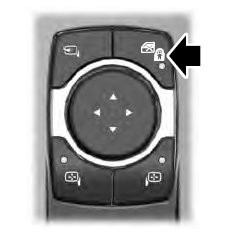
    Lincoln Aviator. Child Safety Locks

    The child safety lock control is on the driver door.

    Press the control to switch the child safety locks on. Press the control again to switch them off. A light on the child safety control illuminates when you switch them on.

    read more

     
    Copyright © 2024 www.liaviator2.com