Lincoln Aviator 2020-2026 Service Manual / Chassis / Steering System / Steering Wheel and Column Electrical Components / General Procedures - Steering Column Multifunction Switch Adjustment
Lincoln Aviator: Steering Wheel and Column Electrical Components / General Procedures - Steering Column Multifunction Switch Adjustment
Adjustment
-
Using a diagnostic scan tool, retrieve and diagnose all SECM Diagnostic Trouble Codes (DTCs).
Refer to: Adaptive Steering (211-02 Power Steering, Diagnosis and Testing).
-
Using a diagnostic scan tool, retrieve and diagnose all SASM Diagnostic Trouble Codes (DTCs).
Refer to: Anti-Lock Brake System (ABS) and Stability Control (206-09 Anti-Lock Brake System (ABS) and Stability Control, Diagnosis and Testing).
-
Position the vehicle onto an alignment rack with the front wheels in the straight ahead position.
-
Turn the engine off.
-
Remove the steering wheel.
Refer to: Steering Wheel (211-04 Steering Column, Removal and Installation).
-
Inspect the steering wheel end of the steering column shaft and the white SCCM ring.
-
Confirm the steering column shaft hex flat is horizontal, the white SCCM ring tab is at the 12 o'clock position and the turn signal tab is centered on the disc activator as shown above.
.jpg) |
-
If the items are not positioned as shown, loosen the
tie-rod jamb nuts and rotate the tie rods until the items are positioned
as shown. Make sure to adjust both sides equally.
Refer to: Front Toe Adjustment - Vehicles With: Adaptive Steering (204-00 Suspension System - General Information, General Procedures).
-
Confirm the steering column shaft hex flat is horizontal, the white SCCM ring tab is at the 12 o'clock position and the turn signal tab is centered on the disc activator as shown in Step 7.
-
Install the steering wheel. This requires manually
releasing the service lock and rotating the clockspring into position on
the SCCM yellow posts.
Refer to: Steering Wheel (211-04 Steering Column, Removal and Installation).
.jpg) |
-
Set the ignition ON, engine off.
-
NOTE: Make sure the front wheels are in the straight ahead position during the trim procedure.
Using a diagnostic scan tool, carry out the steering motor angle trim routine. Follow all on-screen instructions.
-
Carry out the front toe adjustment procedure.
Refer to: Front Toe Adjustment - Vehicles With: Adaptive Steering (204-00 Suspension System - General Information, General Procedures).
-
Start the engine.
-
Confirm correct steering wheel clear vision, turn signal
operation and equal steering wheel rotation from lock-to-lock.
 Diagnosis and Testing - Steering Wheel and Column Electrical Components
Diagnostic Trouble Code (DTC) Chart
Diagnostics in this manual assume a certain skill level and knowledge of Ford-specific diagnostic practices. REFER to: Diagnostic Methods (100-00 General Information, Description and Operation)...
 Removal and Installation - Ignition Switch - Vehicles With: Keyless Vehicle System
Removal
NOTE:
Removal steps in this procedure may contain installation details.
Remove and disconnect the switch pack.
Remove trim panel...
Other information:
Lincoln Aviator 2020-2026 Owners Manual: Garage Door Opener
HomeLink Wireless Control System WARNING: Do not use the system with any garage door opener that does not have the safety stop and reverse feature as required by U.S. Federal Safety Standards (this includes any garage door opener manufactured before April 1, 1982)...
Lincoln Aviator 2020-2026 Service Manual: Description and Operation - Climate Control System - Component Location
I..
Categories
- Manuals Home
- Lincoln Aviator Owners Manual
- Lincoln Aviator Service Manual
- Disabling Auto-Start-Stop
- Keyless Entry
- Child Safety Locks
- New on site
- Most important about car
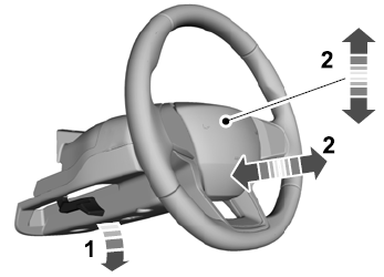
Adjusting the Steering Wheel - Vehicles With: Manual Adjustable Steering Column
WARNING: Do not adjust the steering wheel when your vehicle is moving.
Note: Make sure that you are sitting in the correct position.
Unlock the steering column. Adjust the steering wheel to the desired position.
Copyright © 2026 www.liaviator2.com
