Lincoln Aviator 2020-2026 Service Manual / Powertrain / Engine / Engine System - General Information / General Procedures - Valve Guide Inner Diameter
Lincoln Aviator: Engine System - General Information / General Procedures - Valve Guide Inner Diameter
Check
NOTE: Refer to the appropriate Section 303-01 for the specification.
-
NOTE: Valve guides tend to wear in an hourglass pattern. The ball gauge can be inserted into the combustion chamber side of the valve guide, if necessary.
-
Use a ball gauge to determine the inside diameter of
the valve guides in 2 directions at the top, middle and bottom of the
valve guide.
-
Measure the ball gauge with a micrometer.
-
If the valve guide is not within specifications, install a new cylinder head assembly.
-
Use a ball gauge to determine the inside diameter of
the valve guides in 2 directions at the top, middle and bottom of the
valve guide.
.jpg) |
 General Procedures - Spark Plug Inspection
Inspection
NOTE:
Dropped spark plugs should always be discarded.
Unfired
An unfired spark plug should appear very clean
with a pure nickel finish to the threads and ground strap...
 General Procedures - Valve Stem Diameter
Check
NOTE:
Refer to the appropriate Section 303-01 for the specification.
Measure the diameter of each intake and exhaust valve
stem at the points shown...
Other information:
Lincoln Aviator 2020-2026 Service Manual: Description and Operation - Parking Aid - System Operation and Component Description
System Operation Active Park Assist System Diagram Item Description 1 PCM 2 with 14 or 28 speaker system 3 GWM 4 TRM 5 APIM 6 Audio system display 7 SCCM 8 PSCM 9 ATCM 10 ABS module 11 BCM 12 ACM 13 IPC 14 DSP 15 Rear door speakers 16 Front door speakers 17 IPMB 18 Right front active sensor 19 Left front active sensor 20 Right rear active sensor 21 Left rear active sensor 22 PAM Network Message Chart IPMB Network Input Messages Broadcast Message Originating Module Message Purpose ABS active ABS module Disables the active park assist if an ABS activation occurs...
Lincoln Aviator 2020-2026 Service Manual: Removal and Installation - Instrument Panel Upper Section
Special Tool(s) / General Equipment Interior Trim Remover Removal NOTE: Removal steps in this procedure may contain installation details. Depower the SRS. Refer to: Supplemental Restraint System (SRS) Depowering (501-20B Supplemental Restraint System, General Procedures)...
Categories
- Manuals Home
- Lincoln Aviator Owners Manual
- Lincoln Aviator Service Manual
- Child Safety Locks
- Anti-Theft Alarm
- Description and Operation - Body and Frame
- New on site
- Most important about car
Fastening the Seatbelts
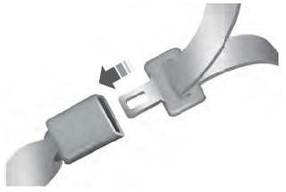
The front outboard and rear safety restraints in the vehicle are combination lap and shoulder belts.
Insert the belt tongue into the proper buckle (the buckle closest to the direction the tongue is coming from) until you hear a snap and feel it latch. Make sure that you securely fasten the tongue in the buckle.
Copyright © 2026 www.liaviator2.com
