Lincoln Aviator: Charging the High Voltage Battery - Plug-In Hybrid Electric Vehicle (PHEV) / CAUTION: TO REDUCE THE RISK OF FIRE
Use a three-prong AC outlet that is properly grounded, 15-20 amps or greater, and in good condition. Use a dedicated line. You cannot have other appliances connected to the same circuit. If you do not use a dedicated circuit, the circuit breaker could trip or open. If you do not have a dedicated circuit, contact a licensed professional electrician for proper installation.
Note: Make sure the electrical source meets the requirements for the high-voltage batteries to charge.
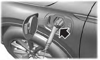
Make sure that the dual-voltage charging cord is completely unwrapped before charging. Always plug the cord into the AC outlet before connecting the charged coupler into the charge port on your vehicle.
Note: If the power indicator light is off after plugging in the dual-voltage charging cord and you cannot determine a charge status, use a different outlet.
Note: Store the dual-voltage charging cord in a clean dry place between the temperature of -39.9–157.9°F (-40–70°C)
Note: For further information on the dual-voltage charging cord , please refer to the user manual provided with the dual-voltage charging cord.
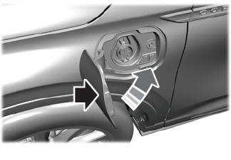
Charge Port
The charge port is between the front left-hand side door and the front left-hand wheel well. To open, press the center right edge of the charge port door, and then release.
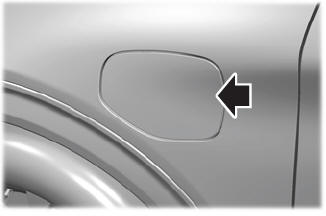
Note: Do not force the charge port door open or closed. Forcing the door open or closed damages the charge port.
The charge status indicator around the charge port indicates the charge status of the high voltage battery in your vehicle.
Divided into five zones, the charge status indicator displays the state of charge in 20 percent increments.
We use the color white as a courtesy light to help with plugging in and to acknowledge actions such as plugging in, unplugging or pressing the charge times button.
Blue is used when you plug the vehicle in and are either charging or waiting to charge.
Orange indicates charge faults.
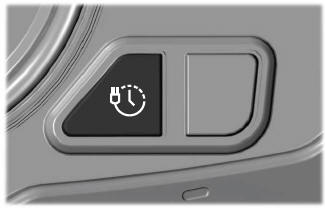
Charge Times Button
Use the charge times button to either turn off or turn on your charge times settings for this location. Select charge settings on the home page of your touchscreen or under the vehicle settings menu to access charge preferences.
Charging

To charge the high-voltage battery:
- Put the vehicle in park (P).
- Press the center right edge of the charge port door and then release to open the door.
- Plug the charging coupler into the charge
port receptacle on your vehicle. Make
sure the button clicks confirming that you
have completely engaged the coupler.
Note: Put your vehicle in park (P) to charge, and for the charge status indicator to illuminate.
Note: Pump and fan noise could be present when charging the high voltage battery. The pump and fan noise is normal as it circulates liquid and keeps your high voltage battery cool while charging.
- Verify that the cord acknowledgment feature activates. This indicates the beginning of a normal charge cycle. The charge status indicator lights up each zone alternately from bottom to top and from bottom to top again.
- If using a charging station, follow the instructions on the charge station to begin the charging process.
The charge status indicator displays how far along the charge is:
- When the bottom zone is pulsing, the charge is between 0-20 percent.
- When the bottom zone illuminates and the next is pulsing, the charge is between 20-40 percent.
- When two zones illuminate and the next is pulsing, the charge is between 40-60 percent.
- When three zones illuminate and the next is pulsing, the charge is between 60-80 percent.
- When four zones illuminate and the top zone is pulsing, the charge is between 80-100 percent.
- When all zones illuminate, the charge is 100 percent.
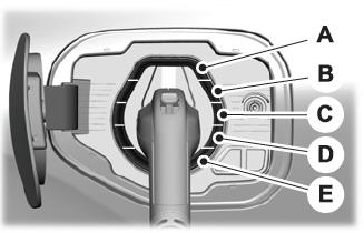
- 80%-100% state of charge.
- 60%-80% state of charge.
- 40%-60% state of charge.
- 20%-40% state of charge.
- 0%-20% state of charge.
Note: When charging stops, the charge status indicator shows all the completed zones solidly lit up in a blue color for 30 seconds before turning off. For example, if charging stops at 70 percent, then the bottom three zones light up solidly to indicate a battery charge level of at least 60 percent but less than 80 percent. Charging stops when complete or when paused due to preferred charge settings or charge station actions.
Note: If the charge status indicator does not light up or pulse after plugging in, please verify that the charge port light setting is On. If you do not wish to have the charge status indicator light up at all while charging, then you can switch it Off. See charge port light under vehicle settings on your touchscreen.

Note: You can identify charging faults by the color orange on the charge status indicator. Faults can occur within the vehicle charging system or outside the vehicle, such as with the charge cord, charge station or electrical supply.
Note: If the system detects a fault in the vehicle charging system at any point in a charge cycle, the entire charge status indicator lights up solidly in an orange color for 30 seconds and then turns off. If this happens, unplug the charging coupler and then plug it back into the charge port receptacle. If the problem persists, have your vehicle checked as soon as possible.
Note: If the system detects a fault outside the vehicle, such as with the charge station or charge cord, the entire charge status indicator flashes continuously for 30 seconds and then turns off. If this happens, check the charge cord and the charge station or electrical supply.
Locking the Charging Coupler
Note: You need a padlock or a combination lock with a shackle diameter of 0.2 in (5 mm) or less, and the straight portion of the shackle of 1.0 in (25.4 mm) of length or more.
- Insert the lock through the hole in the charging coupler button.
- Lock the padlock or combination lock.
Waiting to Charge

Note: Select charge settings on the home page of the touchscreen or under the vehicle settings menu to access charge preferences.
Charging may not begin upon plugging in if you have set up preferred charge times for this vehicle location. Your vehicle could delay charging to take advantage of off-peak electricity rates. Your vehicle optimizes the charge schedule to be complete by your next departure time.
When waiting to charge, plugged in and not currently charging, the charge status indicator shows the present state of charge of the high voltage battery by lighting up all completed zones for 30 seconds before turning off. For example, if the battery is at 70 percent charge then the bottom three zones solidly light up to indicate a battery charge level of at least 60 percent but less than 80 percent. When the current state of charge is less than 20 percent, none of the zones light up.
Note: When your vehicle is waiting to charge, the charge status indicator turns off 30 seconds after displaying the present state of charge. When your vehicle begins charging, the charge status indicator turns on and displays the status of the charge, as described above.
Disconnecting the Charging Coupler
- If you have installed a padlock or combination lock, then remove it.
- Press the button on the charging coupler.
- While holding the button, remove the
charging coupler from the charge port
receptacle.
- Press the center right edge of the charge port door to close.
Note: Do not pull the wall plug from the wall when your vehicle is charging. Doing so could damage the outlet and the cord.
 OPERATION INSTRUCTIONS
Read all the instructions before using this
product.
Supervise this device when in use around
children.
Do not put fingers into the electric vehicle
connector...
 MOVING AND STORAGE INSTRUCTIONS
Make sure that you completely wrap the
dual-voltage charging cord after charging.
When complete, replace the dual-voltage
charging cord in the luggage compartment...
Other information:
Lincoln Aviator 2020-2026 Service Manual: Diagnosis and Testing - Exhaust System
Diagnostic Trouble Code (DTC) Chart Diagnostics in this manual assume a certain skill level and knowledge of Ford-specific diagnostic practices. REFER to: Diagnostic Methods (100-00 General Information, Description and Operation). Diagnostic Trouble Code Chart Module DTC Description Action PCM P0544:00 Exhaust Gas Temperature Sensor Circuit (Bank 1 Sensor 1): No Sub Type Information GO to Pinpoint Test RB PCM P0545:00 Exhaust Gas Temperature Sensor Circuit Low (Bank 1 Sensor 1): No Sub Type Information GO to Pinpoint Test RB PCM P0546:00 Exhaust Gas Temperature Sensor Circuit High (Bank 1 Sensor 1): No Sub Type Information GO to Pinpoint Test RB PCM P0547:00 Exhaust Gas Temperature Sensor Circuit (Bank 2 Sensor 1): No Sub Type Information GO to Pinpoint Test RB PCM P0548:00 Exhaust Gas Temperature Sensor Circuit Low (Bank 2 Sensor 1): No Sub Type Information GO to Pinpoint Test RB PCM P0549:00 Exhaust Gas Temperature Sensor Circuit High (Bank 2 Sensor 1): No Sub Type Information GO to Pinpoint Test RB Global Customer Symptom Code (GCSC) Chart Diagnostics in this manual assume a certain skill level and knowledge of Ford-specific diagnostic practices...
Lincoln Aviator 2020-2026 Owners Manual: Engine Compartment Fuse Box
WARNING: Always disconnect the battery before servicing high current fuses. WARNING: To reduce risk of electrical shock, always replace the cover to the power distribution box before reconnecting the battery or refilling fluid reservoirs. The engine compartment fuse box is under the driver side leaf screen in the engine compartment...
Categories
- Manuals Home
- Lincoln Aviator Owners Manual
- Lincoln Aviator Service Manual
- Disabling Auto-Start-Stop
- Description and Operation - Jacking and Lifting
- Drive Modes
- New on site
- Most important about car
Adjusting the Steering Wheel - Vehicles With: Manual Adjustable Steering Column
WARNING: Do not adjust the steering wheel when your vehicle is moving.
Note: Make sure that you are sitting in the correct position.
Unlock the steering column. Adjust the steering wheel to the desired position.