Lincoln Aviator: Personalized Settings / Information On Demand (If Equipped)

Note: On Demand information appears on the right-hand side of your instrument cluster in single gauge view and in the center of your instrument cluster in dual gauge view when certain drive modes are switched on.

Note: Pure EV information is only available when you switch on the Pure EV drive mode.

Lincoln Aviator. Information On Demand (If Equipped)

Lincoln Aviator. Information On Demand (If Equipped)

Trip 1 and 2

Provides trip timer, trip average fuel economy, total trip distance traveled, and distance traveled on electric power only with the engine off.

Press and hold the folder button to reset.

This Trip

Provides trip timer, trip average fuel economy, total trip distance traveled, and distance traveled on electric power only with the engine off. If the gasoline engine has not turned on during the trip then trip average fuel economy is not shown. This Trip automatically resets each time you start your vehicle.

Fuel Economy

An Instant Fuel Economy gauge is provided along with Average Fuel Economy. Average fuel economy is continuously averaged since the last reset.

Both electric only and hybrid operation are included in the calculation. More electric only driving will result in greater average fuel economy.

While viewing this screen you can reset your average fuel economy by pressing and holding the folder button.

When the gasoline engine is off the instant fuel economy gauge is replaced with a electric driving message.

EV Coach

EV Coach can help you to get the most out of your vehicle’s electric driving and regenerative braking capabilities.

When you are accelerating or maintaining speed you will see a blue or white solid bar indicating vehicle power. You may also see a blue rectangular box which shows the power level at which the engine will turn on.

  • When your power level is within the box the color of the bar will be blue. This means you are in Electric operation and the engine is off.
  • When your power level is outside of the box the color of the bar will be white. This means you are in Hybrid operation with a combination of the electric motor and the engine providing vehicle power.

When you are decelerating with either your foot off the accelerator pedal or on the brake pedal you will see a green or white solid bar indicating the power being used to slow down the vehicle. You may also see a green rectangular box which shows the amount of power that can be recaptured by the regenerative braking system and returned to the high voltage battery.

When your power level is completely within the box the color of the bar will be all green. This means that the regenerative braking system is being used to efficiently slow the vehicle down and return the maximum percentage of energy to the high voltage battery.

When your power level is outside of the green box then the bar will be white. This means that both the regenerative braking system and conventional braking system are being used.

Electric Efficiency

This screen shows your average driving distance per kWh of electricity used on your hybrid vehicle. The value is calculated only when your available electric range is being used and the gasoline engine is off.

Distance per full charge is also shown. This is an estimate of the electric range you would have if you plugged in and fully charged your vehicle right now. The higher your electric efficiency, the higher your distance per full charge.

Your electric efficiency is affected by your driving style and route, climate control use, outside temperature and other factors. Best efficiency is achieved in mild ambient temperatures with mild to moderate acceleration and braking, moderate speeds and low climate control usage.

    Personalized Settings

    ..

    Information Messages

    Move the selector switch to the right to acknowledge and remove some messages from the information display. Other messages will be removed automatically after a short time...

    Other information:

    Lincoln Aviator 2020-2025 Service Manual: Description and Operation - Instrument Panel and Interior Switches Illumination - System Operation and Component Description


    System Operation System Diagram - Networked Illumination - Doors NOTE: Not all vehicles come equipped with all the items listed below. The door latch modules are identified as follows: Left front door - DCME Right front door - DCMF Left rear door - DCMG Right rear door - DCMH Item Description 1 MS-CAN 2 DCME 3 Light sensor 4 DCMF 5 DCMH 6 DDM 7 PDM 8 RF door lock switch 9 RF door window control switch 10 LF door window control switch 11 RR door window control switch 12 LR door window control switch 13 LF door lock switch 14 RR door lock switch 15 LR door lock switch 16 GWM 17 DCMG 18 LH front interior door latch switch 19 RH front interior door latch switch 20 LH rear interior door latch switch 21 RH rear interior door latch switch 22 LIN 23 LIN 24 HS-CAN1 25 BCM 26 Dimmer switch 27 Headlamp switch System Diagram - Networked Illumination - Steering Wheel Switches Item Description 1 Light sensor 2 RH lower steering wheel switch 3 RH upper steering wheel switch 4 LH lower steering wheel switch 5 LH upper steering wheel switch 6 SIMA 7 Upshift paddle switch 8 Downshift paddle switch 9 HS-CAN2 10 GWM 11 HS-CAN1 12 LIN 13 BCM 14 Dimmer switch 15 Headlamp switch System Diagram - Networked Illumination - Other Modules Item Description 1 FCIM 2 APIM 3 Light sensor 4 ACM 5 IPC 6 FDIM 7 without Touchscreen 8 FCDIM 9 RHVAC 10 RACM 11 LIN 12 HS-CAN1 13 MS-CAN 14 HS-CAN3 15 GWM 16 Dimmer switch 17 Headlamp switch 18 BCM Network Message Chart   Module Network Input Messages - ACM, APIM, DCME, DCMF, DCMG, DCMH, DDM, FCIM, RACM, RHVAC, SIMA, GWM, IPC and PDM...

    Lincoln Aviator 2020-2025 Service Manual: Diagnosis and Testing - Headlamps


    Diagnostic Trouble Code (DTC) Chart Diagnostics in this manual assume a certain skill level and knowledge of Ford-specific diagnostic practices. REFER to: Diagnostic Methods (100-00 General Information, Description and Operation).   Diagnostic Trouble Code Chart Module   DTC Description Action   BCM B14E0:11 Exterior Lamps Power Supply "C": Circuit Short to Ground   GO to Pinpoint Test A   BCM B14E0:15 Exterior Lamps Power Supply "C": Circuit Short to Battery or Open   GO to Pinpoint Test A   BCM B14E1:11 Exterior Lamps Power Supply "D": Circuit Short to Ground   GO to Pinpoint Test A   BCM B14E1:15 Exterior Lamps Power Supply "D": Circuit Short to Battery or Open   GO to Pinpoint Test A   BCM B14E2:11 Exterior Lamps Power Supply "E": Circuit Short to Ground   GO to Pinpoint Test B   BCM B14E2:15 Exterior Lamps Power Supply "E": Circuit Short to Battery or Open   GO to Pinpoint Test B   BCM B14E3:11 Exterior Lamps Power Supply "F": Circuit Short to Ground   GO to Pinpoint Test B   BCM B14E3:15 Exterior Lamps Power Supply "F": Circuit Short to Battery or Open   GO to Pinpoint Test B   BCM B14E5:01 Left Front Enhanced Exterior Lighting System: General Electrical Failure   GO to Pinpoint Test S   BCM B14E5:08 Left Front Enhanced Exterior Lighting System: Bus Signal / Message Failure   GO to Pinpoint Test S   BCM B14E5:49 Left Front Enhanced Exterior Lighting System: Internal Electronic Failure   GO to Pinpoint Test S   BCM B14E5:55 Left Front Enhanced Exterior Lighting System: Not Configured   GO to Pinpoint Test S   BCM B14E7:01 Right Front Enhanced Exterior Lighting System: General Electrical Failure   GO to Pinpoint Test S   BCM B14E7:08 Right Front Enhanced Exterior Lighting System: Bus Signal / Message Failure   GO to Pinpoint Test S   BCM B14E7:49 Right Front Enhanced Exterior Lighting System: Internal Electronic Failure   GO to Pinpoint Test S   BCM B14E7:55 Right Front Enhanced Exterior Lighting System: Not Configured   GO to Pinpoint Test S   BCM B1533:02 Headlamp Switch Module: General Signal Failure   GO to Pinpoint Test A   BCM B1533:08 Headlamp Switch Module: Bus Signal / Message   GO to Pinpoint Test A   BCM B1533:49 Headlamp Switch Module: Internal Electronic Failure   GO to Pinpoint Test A   BCM B1533:56 Headlamp Switch Module: Invalid / Incompatible Configuration   GO to Pinpoint Test A   BCM B1D00:11 Left Low Beam: Circuit Short To Ground   GO to Pinpoint Test A   BCM B1D00:15 Left Low Beam: Circuit Short To Battery Or Open   GO to Pinpoint Test A   BCM B1D01:11 Right Low Beam: Circuit Short To Ground   GO to Pinpoint Test A   BCM B1D01:15 Right Low Beam: Circuit Short To Battery Or Open   GO to Pinpoint Test A   BCM B1D02:11 Left High Beam Circuit: Circuit Short To Ground   GO to Pinpoint Test B   BCM B1D02:15 Left High Beam Circuit: Circuit Short To Battery Or Open   GO to Pinpoint Test B   BCM B1D03:11 Right High Beam Circuit: Circuit Short To Ground   GO to Pinpoint Test B   BCM B1D03:15 Right High Beam Circuit: Circuit Short To Battery Or Open   GO to Pinpoint Test B   HCM B1041:04 Levelling Control: System Internal Failure   GO to Pinpoint Test H   HCM B1041:54 Levelling Control: Missing Calibration   GO to Pinpoint Test H   HCM B1087:83 LIN Bus "A": Value of Signal Protection Calculation Incorrect   GO to Pinpoint Test F   HCM B1087:83 LIN Bus "A": Value of Signal Protection Calculation Incorrect   GO to Pinpoint Test G   HCM B1087:86 LIN Bus "A": Signal Invalid   GO to Pinpoint Test F   HCM B1087:86 LIN Bus "A": Signal Invalid   GO to Pinpoint Test G   HCM B1088:83 LIN Bus "B": Value of Signal Protection Calculation Incorrect   GO to Pinpoint Test F   HCM B1088:83 LIN Bus "B": Value of Signal Protection Calculation Incorrect   GO to Pinpoint Test G   HCM B1088:86 LIN Bus "B": Signal Invalid   GO to Pinpoint Test F   HCM B1088:86 LIN Bus "B": Signal Invalid   GO to Pinpoint Test G   HCM B1437:01 Left Levelling Actuator: General Electrical Failure   GO to Pinpoint Test I   HCM B1437:87 Left Levelling Actuator: Missing Message   GO to Pinpoint Test F   HCM B1437:87 Left Levelling Actuator: Missing Message   GO to Pinpoint Test G   HCM B1439:01 Right Levelling Actuator: General Electrical Failure   GO to Pinpoint Test I   HCM B1439:87 Right Levelling Actuator: Missing Message   GO to Pinpoint Test F   HCM B1439:87 Right Levelling Actuator: Missing Message   GO to Pinpoint Test G   HCM B14D9:01 Left Headlamp Light Distribution Actuator: General Electrical Failure   GO to Pinpoint Test I   HCM B14D9:64 Left Headlamp Light Distribution Actuator: Signal Plausibility Failure   GO to Pinpoint Test I   HCM B14D9:87 Left Headlamp Light Distribution Actuator: Missing Message   GO to Pinpoint Test F   HCM B14D9:87 Left Headlamp Light Distribution Actuator: Missing Message   GO to Pinpoint Test G   HCM B14DA:01 Right Headlamp Light Distribution Actuator: General Electrical Failure   GO to Pinpoint Test I   HCM B14DA:64 Right Headlamp Light Distribution Actuator: Signal Plausibility Failure   GO to Pinpoint Test I   HCM B14DA:87 Right Headlamp Light Distribution Actuator: Missing Message   GO to Pinpoint Test F   HCM B14DA:87 Right Headlamp Light Distribution Actuator: Missing Message   GO to Pinpoint Test G   HCM B14DB:01 Left Headlamp Driver Control System: General Electrical Failure   GO to Pinpoint Test I   HCM B14DB:54 Left Headlamp Driver Control System: Missing Calibration   GO to Pinpoint Test I   HCM B14DB:55 Left Headlamp Driver Control System: Not Configured   GO to Pinpoint Test I   HCM B14DB:87 Left Headlamp Driver Control System: Missing Message   GO to Pinpoint Test F   HCM B14DB:87 Left Headlamp Driver Control System: Missing Message   GO to Pinpoint Test G   HCM B14DC:01 Right Headlamp Driver Control System: General Electrical Failure   GO to Pinpoint Test I   HCM B14DC:54 Right Headlamp Driver Control System: Missing Calibration   GO to Pinpoint Test I   HCM B14DC:55 Right Headlamp Driver Control System: Not Configured   GO to Pinpoint Test I   HCM B14DC:87 Right Headlamp Driver Control System: Missing Message   GO to Pinpoint Test F   HCM B14DC:87 Right Headlamp Driver Control System: Missing Message   GO to Pinpoint Test G   HCM B1559:96 Left Headlamp: Component Internal Failure   GO to Pinpoint Test I   HCM B155A:96 Right Headlamp: Component Internal Failure   GO to Pinpoint Test I   HCM B15A6:01 Right Matrix Controller Actuator: General Electrical Failure   GO to Pinpoint Test I   HCM B15A6:87 Right Matrix Controller Actuator: Missing Message   GO to Pinpoint Test F   HCM B15A6:87 Right Matrix Controller Actuator: Missing Message   GO to Pinpoint Test G   HCM B15A7:01 Left Matrix Controller Actuator: General Electrical Failure   GO to Pinpoint Test I   HCM B15A7:87 Left Matrix Controller Actuator: Missing Message   GO to Pinpoint Test F   HCM B15A7:87 Left Matrix Controller Actuator: Missing Message   GO to Pinpoint Test G   HCM B1A59:1C Sensor 5 Volt Supply: Circuit Voltage Out of Range   GO to Pinpoint Test H   HCM B1D64:01 Left Headlamp Swiveling Motor: General Electrical Failure   GO to Pinpoint Test I   HCM B1D64:87 Left Headlamp Swiveling Motor: Missing Message   GO to Pinpoint Test F   HCM B1D64:87 Left Headlamp Swiveling Motor: Missing Message   GO to Pinpoint Test G   HCM B1D65:01 Right Headlamp Swiveling Motor: General Electrical Failure   GO to Pinpoint Test I   HCM B1D65:87 Right Headlamp Swiveling Motor: Missing Message   GO to Pinpoint Test F   HCM B1D65:87 Right Headlamp Swiveling Motor: Missing Message   GO to Pinpoint Test G   HCM B1D68:64 Left Headlamp Swiveling Feedback Sensor: Signal Plausibility Failure   GO to Pinpoint Test I   HCM B1D69:64 Right Headlamp Swiveling Feedback Sensor: Signal Plausibility Failure   GO to Pinpoint Test I   HCM C1A03:12 Left Front Height Sensor: Circuit Short To Battery   GO to Pinpoint Test H   HCM C1A03:14 Left Front Height Sensor: Circuit Short To Ground or Open   GO to Pinpoint Test H   HCM C1A03:29 Left Front Height Sensor: Signal Invalid   GO to Pinpoint Test H   HCM C1A03:64 Left Front Height Sensor: Signal Plausibility Failure   GO to Pinpoint Test H   HCM C1A05:12 Left Rear Height Sensor: Circuit Short To Battery   GO to Pinpoint Test H   HCM C1A05:14 Left Rear Height Sensor: Circuit Short To Ground or Open   GO to Pinpoint Test H   HCM C1A05:29 Left Rear Height Sensor: Signal Invalid   GO to Pinpoint Test H   HCM C1A05:64 Left Rear Height Sensor: Signal Plausibility Failure   GO to Pinpoint Test H   HCM U0121:00 Lost Communication With Anti-Lock Brake System (ABS) Control Module: No Sub Type Information   GO to Pinpoint Test J   HCM U0146:00 Lost Communication With Serial Data Gateway "A": No Sub Type Information   GO to Pinpoint Test K   HCM U0151:00 Lost Communication With Restraints Control Module: No Sub Type Information   GO to Pinpoint Test M   HCM U0212:00 Lost Communication With Steering Column Control Module: No Sub Type Information   GO to Pinpoint Test L   HCM U023A:00 Lost Communication With Image Processing Module A: No Sub Type Information   GO to Pinpoint Test N   HCM U0415:00 Invalid Data Received From Anti-Lock Brake System (ABS) Control Module: No Sub Type Information   GO to Pinpoint Test P   HCM U0429:00 Invalid Data received from Steering Column Control Module: No Sub Type Information   GO to Pinpoint Test P   HCM U0447:00 Invalid Data Received From Serial Data Gateway "A": No Sub Type Information   GO to Pinpoint Test P   HCM U0452:00 Invalid Data Received From Restraints Control Module: No Sub Type Information   GO to Pinpoint Test P   HCM U053B:00 Invalid Data Received From Image Processing Module A: No Sub Type Information   GO to Pinpoint Test P   HCM U2024:51 Control Module Cal-Config Data: Not Programmed   GO to Pinpoint Test O   HCM U2024:57 Control Module Cal-Config Data: Invalid / Incompatible Software Component   GO to Pinpoint Test O   HCM U2100:00 Initial Configuration Not Complete: No Sub Type Information   GO to Pinpoint Test O   HCM U2101:00 Control Module Configuration Incompatible: No Sub Type Information   GO to Pinpoint Test O   HCM U2101:56 Control Module Configuration Incompatible: Invalid / Incompatible Configuration   GO to Pinpoint Test O   HCM U2101:86 Control Module Configuration Incompatible: Signal Invalid   GO to Pinpoint Test O   HCM U2200:45 Control Module Configuration Memory Corrupt: Program Memory Failure   GO to Pinpoint Test O   HCM U3000:45 Control Module: Program Memory Failure   GO to Pinpoint Test O   HCM U3000:46 Control Module: Calibration / Parameter Memory Failure   GO to Pinpoint Test O   HCM U3003:16 Battery Voltage: Circuit Voltage Below Threshold   GO to Pinpoint Test Q   HCM U3003:17 Battery Voltage: Circuit Voltage Above Threshold   GO to Pinpoint Test R   SCCM B124C:96 Turn Indicator Stalk Switch Pack: Component Internal Failure   GO to Pinpoint Test E   SCCM B124C:9E Turn Indicator Stalk Switch Pack: Stuck On   GO to Pinpoint Test E Symptom Chart Symptom Chart: Headlamps Diagnostics in this manual assume a certain skill level and knowledge of Ford-specific diagnostic practices...

    Categories

    Remote Control

    Passive Key

    Lincoln Aviator. Remote Control

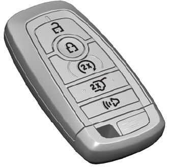
    The passive key operates the power locks and the remote start system. The passive key must be in your vehicle to use the push button start.

    Note: You may not be able to shift out of park (P) unless the passive key is inside your vehicle.

    read more

     
    Copyright © 2025 www.liaviator2.com