
Lincoln Aviator: Catalytic Converter / Readiness for Inspection and Maintenance (I/M) Testing
Some state and provincial and local governments may have Inspection/Maintenance (I/M) programs to inspect the emission control equipment on your vehicle. Failure to pass this inspection could prevent you from getting a vehicle registration.
 If the service engine soon
indicator
is on or the bulb does not work,
your vehicle may need service.
If the service engine soon
indicator
is on or the bulb does not work,
your vehicle may need service.
Your vehicle may not pass the I/M test if the service engine soon indicator is on or not working properly (bulb is burned out), or if the OBD-II system has determined that some of the emission control systems have not been properly checked. In this case, the vehicle is not ready for I/M testing.
If the vehicle’s engine or transmission has just been serviced, or the battery has recently run down or been replaced, the OBD-II system may indicate that the vehicle is not ready for I/M testing. To determine if the vehicle is ready for I/M testing, turn the ignition key to the on position for 15 seconds without cranking the engine. If the service engine soon indicator blinks eight times, it means that the vehicle is not ready for I/M testing; if the service engine soon indicator stays on solid, it means that your vehicle is ready for I/M testing.
The OBD-II system checks the emission control system during normal driving. A complete check may take several days.
If the vehicle is not ready for I/M testing, you can perform the following driving cycle consisting of mixed city and highway driving:
- 15 minutes of steady driving on an expressway or highway followed by 20 minutes of stop-and-go driving with at least four 30-second idle periods.
- Allow your vehicle to sit for at least eight hours with the ignition off. Then, start the vehicle and complete the above driving cycle. The vehicle must warm up to its normal operating temperature. Once started, do not turn off the vehicle until the above driving cycle is complete.
If the vehicle is still not ready for I/M testing, you need to repeat the above driving cycle.
 On-Board Diagnostics (OBD-II)
Your vehicle has a computer known as the
on-board diagnostics system (OBD-II) that
monitors the engine’s emission control
system. The system protects the environment
by making sure that your vehicle continues
to meet government emission standards...

Other information:
Lincoln Aviator 2020-2026 Service Manual: Removal and Installation - Rear Spoiler
Special Tool(s) / General Equipment Interior Trim Remover Removal NOTE: Removal steps in this procedure may contain installation details. Open the rear tail gate. Release the clips and remove the upper liftgate trim panel...
Lincoln Aviator 2020-2026 Owners Manual: Telematics Control Unit
China CMIIT ID: 3019CP0600 CMIIT ID: 2019CP0601 United States and Canada WARNING: Changes or modifications not expressively approved by the party responsible for compliance could void the user's authority to operate the equipment. The term "IC:" before the radio certification number only signifies that Industry Canada technical specifications were met...
Categories
- Manuals Home
- Lincoln Aviator Owners Manual
- Lincoln Aviator Service Manual
- Description and Operation - Body and Frame
- Opening and Closing the Hood
- Interior Lamps
- New on site
- Most important about car
Locking and Unlocking the Doors from Inside
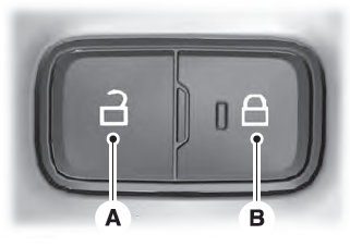
Locking the Doors
Press the lock switch on the door interior trim panel. The doors can no longer be released using the exterior door handle switches and the luggage compartment locks.
