Lincoln Aviator: Intake Air Distribution and Filtering - 3.0L EcoBoost/3.0L EcoBoost – Hybrid (BQ) / Removal and Installation - Air Cleaner Outlet Pipe RH
Removal
NOTICE: The turbocharger compressor vanes can be damaged by even the smallest particles. When removing any turbocharger or engine air intake system component, ensure that no debris enters the system. Failure to do so may result in damage to the turbocharger.
NOTE: Removal steps in this procedure may contain installation details.
Upper air cleaner outlet pipe
-
-
Loosen the clamps and remove the upper air cleaner outlet pipe.
Torque: 42 lb.in (4.8 Nm)
-
Loosen the clamps and remove the upper air cleaner outlet pipe.
.jpg) |
- Loosen the clamps and remove the CAC inlet pipe.
.jpg) |
- Loosen the clamp remove the air cleaner outlet pipe.
.jpg) |
Lower air cleaner outlet pipe
-
Remove the front undershield.
Refer to: Engine Front Undershield (501-02 Front End Body Panels, Removal and Installation).
-
-
Detach the clips.
-
Remove the nut.
Torque: 25 lb.in (2.8 Nm)
-
Detach the clips.
.jpg) |
-
NOTE: Use a 15mm socket located on the cast hex feature to rotate the drive belt tensioner counter-clockwise to release the belt.
-
Rotate the accessory drive belt tensioner clockwise.
-
Position the accessory drive belt aside.
-
Rotate the accessory drive belt tensioner clockwise.
.jpg) |
-
- Disconnect the A/C wiring harness electrical connector.
-
Detach the wiring harness retainer.
-
Remove the lower bolt from the A/C compressor.
Torque: 18 lb.ft (25 Nm)
.jpg) |
-
-
Disconnect the electrical connector.
-
Remove the bolts and position aside A/C compressor.
Torque: 18 lb.ft (25 Nm)
-
Disconnect the electrical connector.
.jpg) |
-
Remove the bolts from the lower air cleaner outlet pipe.
Torque: 93 lb.in (10.5 Nm)
.jpg) |
Installation
-
Inspect the turbocharger or engine air intake system components and clean, if necessary.
-
NOTE: All FEAD components and fasteners must be installed and torque before belt installation.
NOTE: Check the A/C Compressor clutch assembly and crankshaft vibration damper assembly after installation. Lumps in the belt surface indicate ribs are out of pulley grooves and not fully seated in the A/C Compressor clutch assembly and/or crankshaft vibration damper assembly.
After installation, make sure the accessory drive belt is correctly seated on all pulleys.
.jpg) |
-
To install, reverse the removal procedure.
 Removal and Installation - Air Cleaner Outlet Pipe LH
Special Tool(s) /
General Equipment
Hose Clamp Remover/Installer
Removal
NOTICE:
The turbocharger compressor vanes can be damaged by even the
smallest particles...
 Removal and Installation - Charge Air Cooler (CAC)
Removal
NOTICE:
The turbocharger compressor vanes can be damaged by even the
smallest particles. When removing any turbocharger or engine air intake
system component, ensure that no debris enters the system...
Other information:
Lincoln Aviator 2020-2026 Owners Manual: Rear Occupant Alert System Indicators and Audible Warnings
Indicators Message Check rear seats for occupants. Displays when you switch your vehicle off after the alert conditions are met. The message displays for a short period of time. Press Close to acknowledge and remove the message. Audible Warnings Sounds when you switch your vehicle off after the alert conditions are met...
Lincoln Aviator 2020-2026 Service Manual: Removal and Installation - Condenser Inlet Line - 3.0L EcoBoost
Removal NOTICE: During the removal of components, cap, tape or otherwise appropriately protect all openings to prevent the ingress of dirt or other contamination. Remove protective materials prior to installation. NOTE: Removal steps in this procedure may contain installation details...
Categories
- Manuals Home
- Lincoln Aviator Owners Manual
- Lincoln Aviator Service Manual
- Garage Door Opener
- Wireless Accessory Charger (If Equipped)
- Disabling Auto-Start-Stop
- New on site
- Most important about car
Fastening the Seatbelts
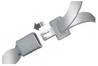
The front outboard and rear safety restraints in the vehicle are combination lap and shoulder belts.
Insert the belt tongue into the proper buckle (the buckle closest to the direction the tongue is coming from) until you hear a snap and feel it latch. Make sure that you securely fasten the tongue in the buckle.
