
Lincoln Aviator 2020-2026 Service Manual / Powertrain / Engine / Intake Air Distribution and Filtering - 3.0L EcoBoost/3.0L EcoBoost – Hybrid (BQ) / Removal and Installation - Charge Air Cooler (CAC)
Lincoln Aviator: Intake Air Distribution and Filtering - 3.0L EcoBoost/3.0L EcoBoost – Hybrid (BQ) / Removal and Installation - Charge Air Cooler (CAC)
Removal
NOTICE: The turbocharger compressor vanes can be damaged by even the smallest particles. When removing any turbocharger or engine air intake system component, ensure that no debris enters the system. Failure to do so may result in damage to the turbocharger.
NOTE: Removal steps in this procedure may contain installation details.
-
Remove the front undershield.
Refer to: Engine Front Undershield (501-02 Front End Body Panels, Removal and Installation).
-
Remove the radiator grille opening panel.
Refer to: Radiator Grille Opening Panel (501-02 Front End Body Panels, Removal and Installation).
-
Remove the air cleaner.
Refer to: Air Cleaner (303-12 Intake Air Distribution and Filtering - 3.0L EcoBoost/3.0L EcoBoost – Hybrid (BQ), Removal and Installation).
-
Loosen the clamp, remove the CAC intake hose.
Torque: 48 lb.in (5.4 Nm)
.jpg) |
-
-
Disconnect the manifold pressure sensor
-
Loosen the clamp and disconnect the CAC outlet hose.
Torque: 48 lb.in (5.4 Nm)
-
Disconnect the manifold pressure sensor
.jpg) |
-
-
Disconnect the quick release coupling.
Refer to: Quick Release Coupling (310-00A Fuel System - General Information - 3.0L EcoBoost, General Procedures).
-
Remove the bolt.
Torque: 71 lb.in (8 Nm)
-
Disconnect the quick release coupling.
.jpg) |
-
-
Dislodge the retainer.
-
Rotate the CAC forward off the lower mounting positions.
-
Dislodge the retainer.
.jpg) |
Installation
-
Inspect the turbocharger or engine air intake system components and clean, if necessary.
-
To install, reverse the removal procedure.
 Removal and Installation - Air Cleaner Outlet Pipe RH
Removal
NOTICE:
The turbocharger compressor vanes can be damaged by even the
smallest particles. When removing any turbocharger or engine air intake
system component, ensure that no debris enters the system...
 Removal and Installation - Charge Air Cooler (CAC) Intake Pipe
Special Tool(s) /
General Equipment
Hose Clamp Remover/Installer
Removal
NOTICE:
The turbocharger compressor vanes can be damaged by even the
smallest particles...
Other information:
Lincoln Aviator 2020-2026 Owners Manual: Information Display Control and Horn
I..
Lincoln Aviator 2020-2026 Service Manual: Diagnosis and Testing - D Clutch
Symptom Chart D Clutch For D clutch operation, REFER to: D Clutch (307-01A Automatic Transmission - 10-Speed Automatic Transmission – 10R60, Description and Operation). D Clutch Condition Possible Sources Action D clutch does not apply SSD mechanically stuck OFF INSTALL a new solenoid...
Categories
- Manuals Home
- Lincoln Aviator Owners Manual
- Lincoln Aviator Service Manual
- General Procedures - Transmission Fluid Drain and Refill
- Body and Paint
- Wireless Accessory Charger (If Equipped)
- New on site
- Most important about car
Activating Intelligent Access
The intelligent access key must be within 3 ft (1 m) of the door or luggage compartment you intend to lock or unlock.
At a Door
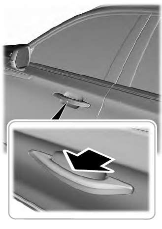
Electronic door handles are on each door. Gently depress the switch inside the exterior door handle to unlock and open the door. An unlock symbol illuminates on the door window trim indicating your vehicle is unlocked.

Copyright © 2026 www.liaviator2.com