
Lincoln Aviator 2020-2026 Service Manual / Body and Paint / Body and Paint / Front End Body Panels / Removal and Installation - Engine Rear Undershield
Lincoln Aviator: Front End Body Panels / Removal and Installation - Engine Rear Undershield
Removal
NOTE: Removal steps in this procedure may contain installation details.
-
Remove the Engine front undershield.
Refer to: Engine Front Undershield (501-02 Front End Body Panels, Removal and Installation).
-
Remove the bolts
Torque: 22 lb.in (2.5 Nm)
.jpg) |
-
-
Remove the retainers
-
Remove the push pins and the engine rear undershield
-
Remove the retainers
.jpg) |
Installation
-
To install, reverse the removal procedure.
 Removal and Installation - Engine Front Undershield
Removal
NOTE:
Removal steps in this procedure may contain installation details.
With the vehicle in NEUTRAL, position it on a hoist.
Refer to: Jacking and Lifting (100-02 Jacking and Lifting)
...
 Removal and Installation - Fender
Special Tool(s) /
General Equipment
Knife
Materials
Name
Specification
Flexible Foam Repair3M™ 08463, LORD Fusor® 121
-
Removal
NOTE:
Removal steps in this procedure may contain installation details...
Other information:
Lincoln Aviator 2020-2026 Service Manual: Removal and Installation - Second Row Seat Climate Control Module
Removal NOTE: Removal steps in this procedure may contain installation details. NOTE: The SCMF (rear seat climate control module) is located under the RH (right-hand) second row seat cushion frame. NOTE: This step is only necessary when installing a new component...
Lincoln Aviator 2020-2026 Service Manual: Removal and Installation - Throttle Body
Removal NOTICE: The turbocharger compressor vanes can be damaged by even the smallest particles. When removing any turbocharger or engine air intake system component, ensure that no debris enters the system. Failure to do so may result in damage to the turbocharger...
Categories
- Manuals Home
- Lincoln Aviator Owners Manual
- Lincoln Aviator Service Manual
- Locking and Unlocking
- Opening and Closing the Hood
- Child Safety Locks
- New on site
- Most important about car
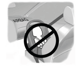
Children and Airbags
WARNING: Airbags can kill or injure a child in a child restraint. Never place a rear-facing child restraint in front of an active airbag. If you must use a forward-facing child restraint in the front seat, move the seat upon which the child restraint is installed all the way back.

Copyright © 2026 www.liaviator2.com