Lincoln Aviator 2020-2026 Service Manual / Body and Paint / Body and Paint / Front End Body Panels / Removal and Installation - Fender
Lincoln Aviator: Front End Body Panels / Removal and Installation - Fender
Special Tool(s) / General Equipment
| Knife |
Materials
| Name | Specification |
|---|---|
| Flexible Foam Repair 3M™ 08463, LORD Fusor® 121 |
- |
Removal
NOTE: Removal steps in this procedure may contain installation details.
NOTE: RH shown, LH similar.
-
Remove the fender splash shield.
Refer to: Fender Splash Shield (501-02 Front End Body Panels, Removal and Installation).
-
Remove the headlamp assembly.
Refer to: Headlamp Assembly (417-01 Exterior Lighting, Removal and Installation).
-
-
Remove the retainers.
-
Gently pull up to release the clips and remove the RH hood air deflector.
-
Remove the retainers.
.jpg) |
-
Remove the retainers and the fender flange finisher.
.jpg) |
-
Remove the nut and the cover.
Torque: 80 lb.in (9 Nm)
.jpg) |
-
Remove the stud.
Torque: 97 lb.in (11 Nm)
.jpg) |
-
Remove the rocker panel moulding.
Refer to: Rocker Panel Moulding (501-08 Exterior Trim and Ornamentation, Removal and Installation).
-
Remove the bolts.
Torque: 97 lb.in (11 Nm)
.jpg) |
-
Remove the bolt.
Torque: 97 lb.in (11 Nm)
.jpg) |
-
NOTE: Follow the unique installation step when installing the fender.
Using a knife, cut the foam sealant between the fender and the body.
Use the General Equipment: Knife
.jpg) |
-
Remove the following items:
-
Remove the bolts.
Torque: 97 lb.in (11 Nm) -
Remove the fender.
-
Remove the bolts.
.jpg) |
-
Remove any excess debris left on the body.
.jpg) |
-
NOTE: This step is only necessary when installing a new component.
Pull and remove the front fender plate assembly.
.jpg) |
Installation
-
To install, reverse the removal procedure.
-
Before installation of the fender, apply a continuous
stream of Fusor® 121 material along the entire span of the baffle-body
attachment area.
Material: Flexible Foam Repair / 3M™ 08463, LORD Fusor® 121
.jpg) |
 Removal and Installation - Engine Rear Undershield
Removal
NOTE:
Removal steps in this procedure may contain installation details.
Remove the Engine front undershield.
Refer to: Engine Front Undershield (501-02 Front End Body Panels, Removal and Installation)...
 Removal and Installation - Fender - Plug-In Hybrid Electric Vehicle (PHEV)
Special Tool(s) /
General Equipment
Knife
Materials
Name
Specification
Flexible Foam Repair3M™ 08463, LORD Fusor® 121
-
Removal
NOTE:
Removal steps in this procedure may contain installation details...
Other information:
Lincoln Aviator 2020-2026 Service Manual: Removal and Installation - Ignition Coil-On-Plug
Special Tool(s) / General Equipment Side Cutter Pliers Removal Remove the retainers and the RH side engine compartment cover. Remove the retainers and the LH side engine compartment cover. Remove the bolts and the suspension support bar...
Lincoln Aviator 2020-2026 Owners Manual: Auto Air Refresh Indicators (If Equipped)
The indicator area is on the touchscreen feature bar and displays one of the following: Indicates blower motor is on for filtering and PM2.5 is low. Indicates the blower motor is on for filtering. Indicates the blower motor is off. Indicates the status is not available...
Categories
- Manuals Home
- Lincoln Aviator Owners Manual
- Lincoln Aviator Service Manual
- Anti-Theft Alarm
- Locking and Unlocking
- Opening and Closing the Hood
- New on site
- Most important about car
Locking and Unlocking the Doors from Inside

Locking the Doors
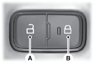
Press the lock switch on the door interior trim panel. The doors can no longer be released using the exterior door handle switches and the luggage compartment locks.
Copyright © 2026 www.liaviator2.com
