Lincoln Aviator: Front Suspension - RWD / Removal and Installation - Front Wheel Bearing and Wheel Hub
Removal
NOTICE: Suspension fasteners are critical parts that affect performance of vital components and systems. Failure of these fasteners may result in major service expense. Use the same or equivalent parts if replacement is necessary. Do not use a replacement part of lesser quality or substitute design. Tighten fasteners as specified.
NOTE: Removal steps in this procedure may contain installation details.
-
Remove the brake disc.
Refer to: Brake Disc (206-03 Front Disc Brake, Removal and Installation).
-
-
Detach the wheel speed sensor wiring retainer.
-
Remove the bolt and position aside the front wheel speed sensor.
-
Detach the wheel speed sensor wiring retainer.
.jpg) |
-
Remove and discard the front wheel bearing and wheel hub bolts and remove the front wheel bearing and wheel hub.
.jpg) |
Installation
-
To install, reverse the removal procedure.
-
NOTICE: The wheel knuckle bore must be clean enough to allow the wheel bearing and wheel hub to seat completely by hand. Do not press or draw the wheel hub and bearing into place or damage to the bearing may occur.
NOTICE: Make sure the wheel hub-to-wheel knuckle mating surfaces are clean and free of any adhesive. Failure to clean the adhesive from both surfaces may cause bearing damage.
Clean and inspect the wheel hub-to-wheel knuckle mating surfaces.
.jpg) |
-
NOTE: Tighten the bolts in a cross pattern.
Position the front wheel bearing and wheel hub and install the 4 new front wheel bearing and wheel hub bolts.
Torque:
Stage 1: 66 lb.ft (90 Nm)
Stage 2: 45°
.jpg) |
-
NOTICE: Make sure that the area around the component is clean and free of foreign material.
-
Position the wheel speed sensor and install the front wheel speed sensor bolt.
Torque: 106 lb.in (12 Nm)
-
Attach the wheel speed sensor wiring retainer.
-
Position the wheel speed sensor and install the front wheel speed sensor bolt.
.jpg) |
-
Install the brake disc.
Refer to: Brake Disc (206-03 Front Disc Brake, Removal and Installation).
 Removal and Installation - Front Stabilizer Bar Link
Removal
NOTICE:
Suspension fasteners are critical parts that affect the
performance of vital components and systems. Failure of these fasteners
may result in major service expense...
 Removal and Installation - Lower Arm Bracket
Special Tool(s) /
General Equipment
Flat Headed Screw Driver
Vehicle/Axle Stands
Removal
NOTICE:
Suspension fasteners are critical parts that affect the
performance of vital components and systems...
Other information:
Lincoln Aviator 2020-2026 Owners Manual: Autolock (If Equipped)
Autolock locks all the doors when: All doors are closed. The ignition is on. You shift into any gear putting your vehicle in motion. Your vehicle reaches a speed greater than 12 mph (20 km/h). Autolock repeats when: You open then close any door while the ignition is on and your vehicle speed is 9 mph (15 km/h) or lower...
Lincoln Aviator 2020-2026 Service Manual: Diagnosis and Testing - Active Grille Shutter
Diagnostic Trouble Code (DTC) Chart Diagnostics in this manual assume a certain skill level and knowledge of Ford-specific diagnostic practices. REFER to: Diagnostic Methods (100-00 General Information, Description and Operation). Diagnostic Trouble Code Chart Module DTC Description Action PCM P059F:00 Active Grille Air Shutter "A" Performance/Stuck Off:No Sub Type Information GO to Pinpoint Test A PCM P05A1:00 Active Grille Air Shutter "A" Position Sensor Minimum/Maximum Stop Performance:No Sub Type Information GO to Pinpoint Test A PCM P05A2:00 Active Grille Air Shutter "A" Control Circuit/Open:No Sub Type Information GO to Pinpoint Test A PCM P05A7:00 Active Grille Air Shutter "A" Supply Voltage Circuit Low:No Sub Type Information GO to Pinpoint Test A PCM P05AE:00 Active Grille Air Shutter "B" Performance/Stuck Off:No Sub Type Information GO to Pinpoint Test A PCM P05B0:00 Active Grille Air Shutter "B" Position Sensor Minimum/Maximum Stop Performance:No Sub Type Information GO to Pinpoint Test A PCM P05B1:00 Active Grille Air Shutter "B" Control Circuit/Open:No Sub Type Information GO to Pinpoint Test A PCM P05B6:00 Active Grille Air Shutter "B" Supply Voltage Circuit Low:No Sub Type Information GO to Pinpoint Test A PCM P05C0:00 Active Grille Air Shutter Module "A" Over Temperature:No Sub Type Information GO to Pinpoint Test A PCM P05C1:00 Active Grille Air Shutter Module "B" Over Temperature:No Sub Type Information GO to Pinpoint Test A PCM U0046:00 Vehicle Communication Bus C:No Sub Type Information GO to Pinpoint Test A PCM U0284:00 Lost Communication with Active Grille Air Shutter Module "A":No Sub Type Information GO to Pinpoint Test A PCM U0285:00 Lost Communication with Active Grille Air Shutter Module "B":No Sub Type Information GO to Pinpoint Test A Symptom Chart(s) Symptom Chart: Active Grille Shutter Diagnostics in this manual assume a certain skill level and knowledge of Ford-specific diagnostic practices...
Categories
- Manuals Home
- Lincoln Aviator Owners Manual
- Lincoln Aviator Service Manual
- Fuel Quality
- Changing the Front Wiper Blades - Vehicles With: Heated Wiper Blades
- Anti-Theft Alarm
- New on site
- Most important about car
Remote Control
Passive Key

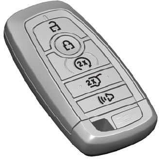
The passive key operates the power locks and the remote start system. The passive key must be in your vehicle to use the push button start.
Note: You may not be able to shift out of park (P) unless the passive key is inside your vehicle.
