Lincoln Aviator 2020-2026 Service Manual / Body and Paint / Body and Paint / Interior Trim and Ornamentation / Removal and Installation - Loadspace Trim Panel
Lincoln Aviator: Interior Trim and Ornamentation / Removal and Installation - Loadspace Trim Panel
Special Tool(s) / General Equipment
| Interior Trim Remover |
Removal
NOTE: LH shown, RH similar.
-
Remove the following items:
-
Remove the rear scuff plate trim panel.
Refer to: Rear Scuff Plate Trim Panel (501-05 Interior Trim and Ornamentation, Removal and Installation).
-
Remove the D-pillar trim panel.
Refer to: D-Pillar Trim Panel (501-05 Interior Trim and Ornamentation, Removal and Installation).
-
Remove the rear scuff plate trim panel.
-
NOTE: Seats removed for clarity.
Remove the tie down hooks.
-
Remove the tie down hook bolt cover.
-
Remove the tie down hook bolt.
Torque: 44 lb.in (5 Nm)
-
Remove the tie down hook bolt cover.
.jpg) |
-
Position the liftgate weatherstrip aside.
.jpg) |
Left hand side
-
NOTE: Seats removed for clarity.
Release the clips and remove the loadspace trim panel.
Use the General Equipment: Interior Trim Remover
.jpg) |
Right hand side
-
NOTE: Seats removed for clarity.
Remove the loadspace trim panel.
-
Release the loadspace trim panel clips.
Use the General Equipment: Interior Trim Remover
-
Disconnect the luggage compartment interior lamp electrical connector.
-
If equipped.
Disconnect the power fold seat control switch electrical connector.
-
Disconnect the luggage compartment power point electrical connector.
-
Release the loadspace trim panel clips.
.jpg) |
Installation
-
NOTE: During installation, make sure the seatbelt webbing is not twisted and the seatbelts and buckles are acccessible to the occupants.
To install, reverse the removal procedure.
-
Check the seatbelt system for correct operation.
Refer to: Seatbelt Systems (501-20A Seatbelt Systems, Diagnosis and Testing).
 Removal and Installation - Liftgate Trim Panel
Special Tool(s) /
General Equipment
Interior Trim Remover
Removal
Release the clips and remove the liftgate center upper trim panel...
 Removal and Installation - Rear Door Trim Panel
Special Tool(s) /
General Equipment
Interior Trim Remover
Removal
NOTE:
LH (left hand) shown, RH (right hand) similar.
NOTE:
Removal steps in this procedure may contain installation details...
Other information:
Lincoln Aviator 2020-2026 Service Manual: General Procedures - Engine Cooling System Flushing
Materials Name Specification Motorcraft® Premium Cooling System FlushVC-1 ESR-M14P7-A Flushing WARNING: Always allow the engine to cool before opening the cooling system. Do not unscrew the coolant pressure relief cap when the engine is operating or the cooling system is hot...
Lincoln Aviator 2020-2026 Owners Manual: Adaptive Cruise Control Precautions - Vehicles With: Adaptive Cruise Control With Lane Centering
Adaptive cruise control precautions apply to lane centering unless stated otherwise or contradicted by a lane centering precaution. WARNING: Do not use the system when towing a trailer. Failure to follow this instruction could result in the loss of control of your vehicle, personal injury or death...
Categories
- Manuals Home
- Lincoln Aviator Owners Manual
- Lincoln Aviator Service Manual
- Child Safety Locks
- Description and Operation - Body and Frame
- Remove and Reinstall the Battery
- New on site
- Most important about car
Locking and Unlocking the Doors from Inside

Locking the Doors
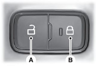
Press the lock switch on the door interior trim panel. The doors can no longer be released using the exterior door handle switches and the luggage compartment locks.
Copyright © 2026 www.liaviator2.com
