Lincoln Aviator: Handles, Locks, Latches and Entry Systems / Removal and Installation - Rear Door Latch
Removal
NOTE: LH (left-hand) side shown, RH (right-hand) side similar.
NOTE: Removal steps in this procedure may contain installation details.
-
NOTE: The PMI process must begin with the current door latch control module installed. If the current door latch control module does not respond to the diagnostic scan tool, the tool may prompt for As-Built Data as part of the repair.
Using a diagnostic scan tool, begin the PMI process for the door latch control module following the on-screen instructions.
-
Remove the rear door window regulator and motor.
Refer to: Rear Door Window Regulator and Motor (501-11 Glass, Frames and Mechanisms, Removal and Installation).
-
NOTE: Rear door shown transparent for clarity.
Remove the aft rear door glass run and bracket.
-
Remove the bolts from the aft rear door glass run and bracket.
Torque: 93 lb.in (10.5 Nm)
-
Remove the aft rear door glass run and bracket.
-
Remove the bolts from the aft rear door glass run and bracket.
.jpg) |
-
NOTE: Rear door shown transparent for clarity.
Disconnect the rear door latch electrical connectors and position the wiring harness aside.
-
Release the rear door wiring harness routing clips.
-
If equipped.
Disconnect the rear door latch cinch motor electrical connector.
-
Disconnect the rear door latch electrical connector and position the wiring harness aside.
-
Release the rear door wiring harness routing clips.
.jpg) |
-
NOTE: Rear door shown transparent for clarity.
Remove rear door latch.
-
If equipped.
Remove the bolt and nuts from the rear door latch cinch motor.
Torque: 48 lb.in (5.4 Nm)
-
Remove the bolts from the rear door latch.
Torque: 106 lb.in (12 Nm)
-
Remove rear door latch.
-
If equipped.
.jpg) |
Installation
-
To install, reverse the removal procedure.
-
Using a diagnostic scan tool, complete the PMI process for the following the door latch control module on-screen instructions
-
Carry out the power door window initialization.
Refer to: Power Door Window Initialization (501-11 Glass, Frames and Mechanisms, General Procedures).
 Removal and Installation - Liftgate Release Switch
Special Tool(s) /
General Equipment
Interior Trim Remover
Removal
Remove the liftgate moulding.
Refer to: Liftgate Moulding (501-08 Exterior Trim and Ornamentation, Removal and Installation)...
 Removal and Installation - Rear Door Latch Cinch Motor
Removal
NOTE:
The rear door latch cinch motor is serviced with the rear door latch.
Remove the rear door latch.
Refer to: Rear Door Latch (501-14 Handles, Locks, Latches and Entry Systems, Removal and Installation)...
Other information:
Lincoln Aviator 2020-2026 Service Manual: General Procedures - Inspection and Repair after a Supplemental Restraint System (SRS) Deployment
Inspection NOTE: Deployable devices such as airbags, pretensioners and inflatable belt inflators, may deploy alone or in various combinations depending on the impact event. NOTE: Always refer to the appropriate workshop manual procedures prior to carrying out vehicle repairs affecting the SRS and seatbelt system...
Lincoln Aviator 2020-2026 Service Manual: Removal and Installation - Battery Monitoring Sensor
Removal NOTE: When the battery is disconnected and connected, some abnormal drive symptoms may occur while the vehicle relearns its adaptive strategy. The vehicle may need to be driven to allow the PCM to relearn the adaptive strategy values. NOTE: Removal steps in this procedure may contain installation details...
Categories
- Manuals Home
- Lincoln Aviator Owners Manual
- Lincoln Aviator Service Manual
- Interior Lamps
- Disabling Auto-Start-Stop
- Remove and Reinstall the Battery
- New on site
- Most important about car
Child Safety Locks
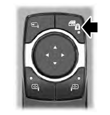
When the child safety locks are set, you cannot open the rear doors from the inside.

The child safety lock control is on the driver door.
Press the control to switch the child safety locks on. Press the control again to switch them off. A light on the child safety control illuminates when you switch them on.
