Lincoln Aviator 2020-2026 Service Manual / Body and Paint / Body and Paint / Seatbelt Systems / Removal and Installation - Second Row Seatbelt Buckle
Lincoln Aviator: Seatbelt Systems / Removal and Installation - Second Row Seatbelt Buckle
Removal
NOTE: Removal steps in this procedure may contain installation details.
NOTE: LH (left-hand) seat shown, RH (right-hand) seat similar.
NOTE: Single seat shown, captain chair similar.
-
Remove the second row seat.
Refer to: Second Row Seat (501-10B Second Row Seats, Removal and Installation).
Refer to: Second Row Seat - Vehicles With: Second Row Captain Chairs (501-10B Second Row Seats, Removal and Installation).
-
Detach and disconnect the second row seatbelt buckle electrical connector.
.jpg) |
-
Detach the second row center seat valance.
-
Release the retainer.
-
Release the retainer.
-
Release the retainer.
.jpg) |
-
Remove the second row seat inboard side shield.
-
Remove the screw.
-
Detach the retainers.
-
Lift the side shield and pull outward.
-
Lift the side shield and pull outward.
-
Push the side shield forward.
-
Remove the screw.
.jpg) |
-
Remove the second row seatbelt buckle.
-
Remove the bolt.
Torque: 30 lb.ft (40 Nm)
-
Position the buckle through the front seat cushion cover.
-
Remove the bolt.
.jpg) |
Installation
NOTE: During installation, make sure the seatbelt webbing is not twisted and the seatbelts and buckles are accessible to the occupants.
-
To install, reverse the removal procedure.
-
Check the seatbelt system for correct operation.
Refer to: Seatbelt Systems (501-20A Seatbelt Systems, Diagnosis and Testing).
 Removal and Installation - Second Row Center Seatbelt Retractor
Removal
NOTE:
Removal steps in this procedure may contain installation details.
Remove the second row center seat.
Refer to: Second Row Center Seat (501-10B Second Row Seats, Removal and Installation)...
 Removal and Installation - Second Row Seatbelt Retractor and Pretensioner
Removal
WARNING:
The following procedure prescribes critical repair steps
required for correct restraint system operation during a crash. Follow
all notes and steps carefully...
Other information:
Lincoln Aviator 2020-2026 Owners Manual: Operating ALL-Wheel drive (AWD) Vehicles with Mismatched Tires
WARNING: Only use replacement tires and wheels that are the same size, load index, speed rating and type (such as P-metric versus LT-metric or all-season versus all-terrain) as those originally provided by Ford. The recommended tire and wheel size may be found on either the Safety Compliance Certification Label (affixed to either the door hinge pillar, door-latch post, or the door edge that meets the door-latch post, next to the driver's seating position), or the Tire Label which is located on the B-Pillar or edge of the driver's door...
Lincoln Aviator 2020-2026 Service Manual: Removal and Installation - Driver Knee Airbag
Removal WARNING: The following procedure prescribes critical repair steps required for correct restraint system operation during a crash. Follow all notes and steps carefully. Failure to follow step instructions may result in incorrect operation of the restraint system and increases the risk of serious personal injury or death in a crash...
Categories
- Manuals Home
- Lincoln Aviator Owners Manual
- Lincoln Aviator Service Manual
- Disabling Auto-Start-Stop
- Resetting the System
- Locking and Unlocking
- New on site
- Most important about car
Child Safety Locks
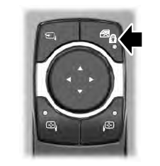
When the child safety locks are set, you cannot open the rear doors from the inside.

The child safety lock control is on the driver door.
Press the control to switch the child safety locks on. Press the control again to switch them off. A light on the child safety control illuminates when you switch them on.
Copyright © 2026 www.liaviator2.com
