Lincoln Aviator 2020-2025 Service Manual / Electrical / Climate Control System / Climate Control System - General Information / Removal and Installation - Thermostatic Expansion Valve Manifold and Tube Assembly - 3.0L EcoBoost
Lincoln Aviator: Climate Control System - General Information / Removal and Installation - Thermostatic Expansion Valve Manifold and Tube Assembly - 3.0L EcoBoost
Removal
NOTICE: During the removal of components, cap, tape or otherwise appropriately protect all openings to prevent the ingress of dirt or other contamination. Remove protective materials prior to installation.
NOTE: Removal steps in this procedure may contain installation details.
-
Recover the refrigerant. Refer to the appropriate Recovery procedure in Group 412.
-
Remove the bolts and the suspension support bar.
Torque: 22 lb.ft (30 Nm)
.jpg) |
-
Remove the PCM.
Refer to: Powertrain Control Module (PCM) (303-14A Electronic Engine Controls - 3.0L EcoBoost/3.0L EcoBoost – Hybrid (BQ), Removal and Installation).
-
Disconnect the harness retainers. Remove the bolts and the PCM mounting bracket.
Torque: 55 lb.in (6.2 Nm)
.jpg) |
-
Remove the RH upper air cleaner outlet pipe.
Refer to: Air Cleaner Outlet Pipe RH (303-12 Intake Air Distribution and Filtering - 3.0L EcoBoost/3.0L EcoBoost – Hybrid (BQ), Removal and Installation).
-
Remove the RH
CAC intake pipe.
Refer to: Charge Air Cooler (CAC) Intake Pipe (303-12 Intake Air Distribution and Filtering - 3.0L EcoBoost/3.0L EcoBoost – Hybrid (BQ), Removal and Installation).
-
-
Remove the condensor outlet line nut and position the line aside.
Torque: 71 lb.in (8 Nm)
-
Remove the A/Ccompressor inlet line nut and position the line aside.
Torque: 159 lb.in (18 Nm)
-
Make sure to cover any open ports to prevent debris from entering the system.
-
Remove the condensor outlet line nut and position the line aside.
.jpg) |
-
Remove the cowl panel.
Refer to: Cowl Panel (501-02 Front End Body Panels, Removal and Installation).
-
-
Remove the wiring harness nuts.
Torque: 80 lb.in (9 Nm)
-
Remove the ground bolt and wiring harness routing bolt.
Torque: 106 lb.in (12 Nm)
-
Disconnect the battery cable ends.
Torque: 48 lb.in (5.4 Nm)
-
Position the wiring harness electrical grommet aside.
-
Disconnect the electrical connector and position aside the battery wiring harness.
-
Remove the wiring harness nuts.
.jpg) |
-
Detach the coolant hose retainer.
.jpg) |
-
NOTE: When removing or installing the fuel injection pump noise insulator, spreading the openings will reduce the risk of damage.
Remove the fuel injection pump noise insulator.
.jpg) |
-
Remove the high-pressure fuel pump shield bolt.
Torque: 18 lb.ft (25 Nm)
.jpg) |
-
Remove the nuts and the high-pressure fuel pump shield .
Torque: 18 lb.ft (25 Nm)
.jpg) |
-
-
Remove the routing bracket retainers.
Torque:
Routing brackets: 89 lb.in (10 Nm)
-
Remove the rear evaporator line nut.
Torque:
Rear evaporator inlet line: 71 lb.in (8 Nm)
-
Remove the thermostatic expansion valve nut and the
rear evaporator line nuts. Remove the thermostatic expansion valve
manifold and tube assembly.
Torque:
Rear evaporator outlet line: 159 lb.in (18 Nm)
TXV: 159 lb.in (18 Nm)
-
Make sure to cover any open ports to prevent debris from entering the system.
-
Remove the routing bracket retainers.
.jpg) |
Installation
-
To install, reverse the removal procedure.
-
NOTICE: Only use the specified material to lubricate the seals.
Install and lubricate new O-ring seals. Refer to the appropriate Specifications in Group 412.
-
Lubricate the refrigerant system with the correct amount
of clean PAG oil. Refer to the appropriate Refrigerant Oil Adding
procedure in Group 412.
 Removal and Installation - Thermostatic Expansion Valve - 3.0L EcoBoost
Removal
NOTICE:
During the removal of components, cap, tape or otherwise
appropriately protect all openings to prevent the ingress of dirt or
other contamination...
Other information:
Lincoln Aviator 2020-2025 Owners Manual: Hazard Flashers
Note: The hazard flashers operate when the ignition is in any position, or if the key is not in the ignition. If used when the vehicle is not running, the battery loses charge. As a result, there may be insufficient power to restart your vehicle...
Lincoln Aviator 2020-2025 Service Manual: Description and Operation - Parking Aid - Overview
Parking Aid Overview Parking Aid - Audible The available parking aid features depend on the vehicle trim level and options selected. The possible audio parking aid configurations are as follows: Front and rear parking aid Front and rear parking aid, plus active park assist and the side sensing system (also known as flank guard) The rear parking aid system sounds a warning tone through the rear audio speakers to alert the driver of stationary objects near the rear bumper when the vehicle is in reverse...
Categories
- Manuals Home
- Lincoln Aviator Owners Manual
- Lincoln Aviator Service Manual
- Garage Door Opener
- Tire Change Procedure
- Description and Operation - Jacking and Lifting
- New on site
- Most important about car
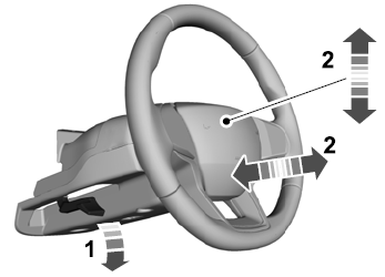
Adjusting the Steering Wheel - Vehicles With: Manual Adjustable Steering Column
WARNING: Do not adjust the steering wheel when your vehicle is moving.
Note: Make sure that you are sitting in the correct position.
Unlock the steering column. Adjust the steering wheel to the desired position.
Copyright © 2025 www.liaviator2.com

