Lincoln Aviator 2020-2026 Service Manual / Electrical / Climate Control System / Climate Control System - General Information / Removal and Installation - Thermostatic Expansion Valve - 3.0L EcoBoost
Lincoln Aviator: Climate Control System - General Information / Removal and Installation - Thermostatic Expansion Valve - 3.0L EcoBoost
Removal
NOTICE: During the removal of components, cap, tape or otherwise appropriately protect all openings to prevent the ingress of dirt or other contamination. Remove protective materials prior to installation.
NOTE: Removal steps in this procedure may contain installation details.
-
Recover the refrigerant. Refer to the appropriate Recovery procedure in Group 412.
-
Remove the bolts and the suspension support bar.
Torque: 22 lb.ft (30 Nm)
.jpg) |
-
Remove the PCM.
Refer to: Powertrain Control Module (PCM) (303-14A Electronic Engine Controls - 3.0L EcoBoost/3.0L EcoBoost – Hybrid (BQ), Removal and Installation).
-
Disconnect the harness retainers. Remove the bolts and the PCM mounting bracket.
Torque: 55 lb.in (6.2 Nm)
.jpg) |
-
Remove the RH upper air cleaner outlet pipe.
Refer to: Air Cleaner Outlet Pipe RH (303-12 Intake Air Distribution and Filtering - 3.0L EcoBoost/3.0L EcoBoost – Hybrid (BQ), Removal and Installation).
-
Remove the RH
CAC intake pipe.
Refer to: Charge Air Cooler (CAC) Intake Pipe (303-12 Intake Air Distribution and Filtering - 3.0L EcoBoost/3.0L EcoBoost – Hybrid (BQ), Removal and Installation).
-
Remove the cowl panel.
Refer to: Cowl Panel (501-02 Front End Body Panels, Removal and Installation).
-
-
Remove the routing bracket retainers.
Torque:
Routing brackets: 89 lb.in (10 Nm)
-
Remove the rear evaporator line nut.
Torque:
Rear evaporator inlet line: 71 lb.in (8 Nm)
-
Remove the thermostatic expansion valve nut and the
rear evaporator line nuts. Position aside the thermostatic expansion
valve manifold and tube assembly.
Torque:
Rear evaporator outlet line: 159 lb.in (18 Nm)
TXV: 159 lb.in (18 Nm)
-
Make sure to cover any open ports to prevent debris from entering the system.
-
Remove the routing bracket retainers.
.jpg) |
-
Remove the bolts and the Thermostatic Expansion Valve (TXV).
Torque: 71 lb.in (8 Nm)
.jpg) |
Installation
-
To install, reverse the removal procedure.
-
NOTICE: Only use the specified material to lubricate the seals.
Install and lubricate new O-ring seals. Refer to the appropriate Specifications in Group 412.
-
Lubricate the refrigerant system with the correct amount
of clean PAG oil. Refer to the appropriate Refrigerant Oil Adding
procedure in Group 412.
 Removal and Installation - Temperature Door Actuator
Removal
Fully lower the glove compartment.
Disconnect the check strap.
Push the stop tabs inward.
Remove the screws and the temperature door actuator...
 Removal and Installation - Thermostatic Expansion Valve Manifold and Tube Assembly - 3.0L EcoBoost
Removal
NOTICE:
During the removal of components, cap, tape or otherwise
appropriately protect all openings to prevent the ingress of dirt or
other contamination...
Other information:
Lincoln Aviator 2020-2026 Owners Manual: Entertainment
Audio Source Radio 1 Add the radio frequency to two decimal places to the command. 2 You can say the Sirius channel name or number such as "Sirius Channel 16" or "Sirius The Pulse". USB and Media Player 1 Add an album name, artist name, audiobook name, genre name, playlist name, podcast name or track name to the command...
Lincoln Aviator 2020-2026 Owners Manual: Using Speed Sign Recognition
Setting the System Speed Warning You can set the system speed warning to alert you when the vehicle speed exceeds the speed limit recognized by the system by a certain speed tolerance. Note: The system remembers the last setting when you start your vehicle...
Categories
- Manuals Home
- Lincoln Aviator Owners Manual
- Lincoln Aviator Service Manual
- Anti-Theft Alarm
- Child Safety Locks
- Wireless Accessory Charger (If Equipped)
- New on site
- Most important about car
Activating Intelligent Access
The intelligent access key must be within 3 ft (1 m) of the door or luggage compartment you intend to lock or unlock.
At a Door
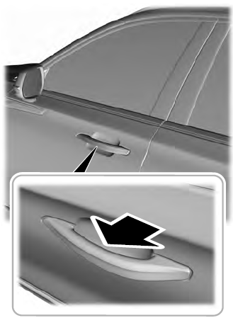
Electronic door handles are on each door. Gently depress the switch inside the exterior door handle to unlock and open the door. An unlock symbol illuminates on the door window trim indicating your vehicle is unlocked.

Copyright © 2026 www.liaviator2.com
