Lincoln Aviator: Blind Spot Information System / Using the Blind Spot Information System

Vehicles with Automatic Transmission The system turns on when all of the following occur:

  • You start your vehicle.
  • You shift into drive (D).
  • The vehicle speed is greater than 6 mph (10 km/h).

Note: The system does not operate in park (P) or reverse (R).

System Lights and Messages

Lincoln Aviator. Using the Blind Spot Information System

When the system detects a vehicle, an alert indicator illuminates in the exterior mirror on the side the approaching vehicle is coming from. If you turn the direction indicator on for that side of your vehicle, the alert indicator flashes.

Note: The system may not alert you if a vehicle quickly passes through the detection zone.

Blocked Sensors

Lincoln Aviator. Using the Blind Spot Information System

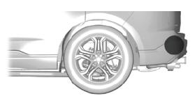
The sensors are behind the rear bumper on both sides of your vehicle.

Note: Keep the sensors free from snow, ice and large accumulations of dirt.

Note: Do not cover the sensors with bumper stickers, repair compound or other objects.

Note: Blocked sensors could affect system performance.

If the sensors become blocked, a message could appear in the information display. The alert indicators remain illuminated but the system does not alert you.

System Errors

If the system detects a fault, a warning lamp illuminates and a message displays.

Switching the System On and Off

To switch the system on or off, adjust the setting. Depending on your vehicle options, the setting could be in the following:

  • Information display.
  • Touchscreen.

When you switch the system off, a warning lamp illuminates and the alert indicators flash twice.

Note: The system remembers the last setting when you start your vehicle.

Note: The system may not correctly operate when towing a trailer. For vehicles with an approved trailer tow module and tow bar, the system turns off when you attach a trailer. For vehicles with an aftermarket trailer tow module or tow bar, we recommend that you switch the system off when you attach a trailer.

To permanently switch the system off, contact an authorized dealer.

    Blind Spot Information System

    WARNING: Do not use the blind spot information system as a replacement for using the interior and exterior mirrors or looking over your shoulder before changing lanes...

    Blind Spot Information System with Trailer Tow (If Equipped)

    The design of the system is to aid you in detecting vehicles that could have entered the detection area zone (A). The detection area is on both sides of your vehicle and trailer, extending rearward from the exterior mirrors to the end of your trailer...

    Other information:

    Lincoln Aviator 2020-2023 Service Manual: Diagnosis and Testing - Vehicle Dynamic Suspension


    Diagnostic Trouble Code (DTC) Chart Diagnostics in this manual assume a certain skill level and knowledge of Ford-specific diagnostic practices. REFER to: Diagnostic Methods (100-00 General Information, Description and Operation).   Diagnostic Trouble Code Chart Module   DTC Description Action   VDM C110C:11 Left Front Damper Solenoid: Circuit Short to Ground   GO to Pinpoint Test D   VDM C110C:12 Left Front Damper Solenoid: Circuit Short to Battery   GO to Pinpoint Test D   VDM C110C:13 Left Front Damper Solenoid: Circuit Open   GO to Pinpoint Test D   VDM C110C:64 Left Front Damper Solenoid:Signal Plausibility Failure   GO to Pinpoint Test D   VDM C110D:11 Right Front Damper Solenoid: Circuit Short to Ground   GO to Pinpoint Test E   VDM C110D:12 Right Front Damper Solenoid: Circuit Short to Battery   GO to Pinpoint Test E   VDM C110D:13 Right Front Damper Solenoid: Circuit Open   GO to Pinpoint Test E   VDM C110D:64 Right Front Damper Solenoid:Signal Plausibility Failure   GO to Pinpoint Test E   VDM C110E:11 Left Rear Damper Solenoid: Circuit Short to Ground   GO to Pinpoint Test F   VDM C110E:12 Left Rear Damper Solenoid: Circuit Short to Battery   GO to Pinpoint Test F   VDM C110E:13 Left Rear Damper Solenoid: Circuit Open   GO to Pinpoint Test F   VDM C110E:64 Left Rear Damper Solenoid:Signal Plausibility Failure   GO to Pinpoint Test F   VDM C110F:11 Right Rear Damper Solenoid: Circuit Short to Ground   GO to Pinpoint Test G   VDM C110F:12 Right Rear Damper Solenoid: Circuit Short to Battery   GO to Pinpoint Test G   VDM C110F:13 Right Rear Damper Solenoid: Circuit Open   GO to Pinpoint Test G   VDM C110F:64 Right Rear Damper Solenoid:Signal Plausibility Failure   GO to Pinpoint Test G   VDM C1124:55 Height Sensor(s):Not Configured   GO to Pinpoint Test U   VDM C1124:56 Height Sensor(s):Invalid/Incompatible Configuration   GO to Pinpoint Test U   VDM C1A03:11 Left Front Height Sensor: Circuit Short to Ground   GO to Pinpoint Test H   VDM C1A03:12 Left Front Height Sensor: Circuit Short to Battery   GO to Pinpoint Test H   VDM C1A03:29 Left Front Height Sensor:Signal Invalid   GO to Pinpoint Test H   VDM C1A03:64 Left Front Height Sensor:Signal Plausibility Failure   GO to Pinpoint Test T   VDM C1A04:11 Right Front Height Sensor: Circuit Short to Ground   GO to Pinpoint Test I   VDM C1A04:12 Right Front Height Sensor: Circuit Short to Battery   GO to Pinpoint Test I   VDM C1A04:29 Right Front Height Sensor:Signal Invalid   GO to Pinpoint Test I   VDM C1A04:64 Right Front Height Sensor:Signal Plausibility Failure   GO to Pinpoint Test T   VDM C1A05:11 Left Rear Height Sensor: Circuit Short to Ground   GO to Pinpoint Test J   VDM C1A05:12 Left Rear Height Sensor: Circuit Short to Battery   GO to Pinpoint Test J   VDM C1A05:29 Left Rear Height Sensor:Signal Invalid   GO to Pinpoint Test J   VDM C1A05:64 Left Rear Height Sensor:Signal Plausibility Failure   GO to Pinpoint Test T   VDM C1A06:11 Right Rear Height Sensor: Circuit Short to Ground   GO to Pinpoint Test K   VDM C1A06:12 Right Rear Height Sensor: Circuit Short to Battery   GO to Pinpoint Test K   VDM C1A06:29 Right Rear Height Sensor:Signal Invalid   GO to Pinpoint Test K   VDM C1A06:64 Right Rear Height Sensor:Signal Plausibility Failure   GO to Pinpoint Test T   VDM P1758:19 Pressure Solenoid Control System Incorrect Current: Circuit Current Above Threshold   GO to Pinpoint Test C   VDM U0100:87 Lost Communication With ECM / PCM: Missing Message   GO to Pinpoint Test M   VDM U0121:87 Lost Communication With Anti-Lock Brake System (ABS) Control Module: Missing Message   GO to Pinpoint Test N   VDM U0131:87 Lost Communication With EPAS module: Missing Message   GO to Pinpoint Test O   VDM U0140:87 Lost Communication With Body Control Module: Missing Message   GO to Pinpoint Test P   VDM U0151:87 Lost Communication With Restraints Control Module: Missing Message   GO to Pinpoint Test Q   VDM U0164:87 Lost Communication With HVAC Control Module:Missing Message   GO to Pinpoint Test R   VDM U023A:87 Lost Communication With Image Processing Module A:Missing Message   GO to Pinpoint Test S   VDM U0401:00 Invalid Data Received from ECM/PCM A:No Sub Type Information   GO to Pinpoint Test W   VDM U0415:00 Invalid Data Received from Anti-Lock Brake System (ABS) Control Module "A":No Sub Type Information   GO to Pinpoint Test X   VDM U0420:00 Invalid Data Received from Power Steering Control Module "A":No Sub Type Information   GO to Pinpoint Test Y   VDM U0422:00 Invalid Data Received From Body Control Module:No Sub Type Information   GO to Pinpoint Test Z   VDM U0424:00 Invalid Data Received From HVAC Control Module:No Sub Type Information   GO to Pinpoint Test AA   VDM U0452:00 Invalid Data Received From Restraints Control Module:No Sub Type Information   GO to Pinpoint Test AB   VDM U053B:00 Invalid Data Received From Image Processing Module A:No Sub Type Information   GO to Pinpoint Test AC   VDM U1000:00 Solid State Driver Protection Active -Driver Disabled:No Sub Type Information   GO to Pinpoint Test V   VDM U200D:11 Control Module Output Power A: Circuit Short to Ground   GO to Pinpoint Test L   VDM U200D:12 Control Module Output Power A: Circuit Short to Battery   GO to Pinpoint Test L   VDM U200E:11 Control Module Output Power B: Circuit Short to Ground   GO to Pinpoint Test L   VDM U200E:12 Control Module Output Power B: Circuit Short to Battery   GO to Pinpoint Test L   VDM U200F:11 Control Module Output Power C:Circuit Short To Ground   GO to Pinpoint Test J   VDM U200F:12 Control Module Output Power C:Circuit Short To Battery   GO to Pinpoint Test J   VDM U201E:11 Control Module Output Power D:Circuit Short To Ground   GO to Pinpoint Test K   VDM U201E:12 Control Module Output Power D:Circuit Short To Battery   GO to Pinpoint Test K   VDM U2024:51 Control Module Cal-Config Data:Not Programmed   GO to Pinpoint Test V   VDM U2100:00 Initial Configuration Not Complete:No Sub Type Information   GO to Pinpoint Test V   VDM U2200:00 Control Module Configuration Memory Corrupt:No Sub Type Information   GO to Pinpoint Test V   VDM U3000:04 Control Module:System Internal Failures   GO to Pinpoint Test V   VDM U3000:49 Control Module:Internal Electronic Failure   GO to Pinpoint Test V   VDM U3003:16 Battery Voltage: Circuit Voltage Below Threshold   GO to Pinpoint Test A   VDM U3003:17 Battery Voltage: Circuit Voltage Above Threshold   GO to Pinpoint Test B Symptom Chart Symptom Chart: Vehicle Dynamic Suspension Diagnostics in this manual assume a certain skill level and knowledge of Ford-specific diagnostic practices...

    Lincoln Aviator 2020-2023 Service Manual: General Procedures - Lead Terminal Repair


    Materials Name Specification Motorcraft® Ultra-Clear Spray Glass CleanerZC-23 ESR-M14P5-A  Repair Bring the vehicle up to at least the specified room temperature or above. NOTE: The new terminal covers the original terminal location, but it must be placed so the terminal conductive areas will be placed on a good conductive base...

    Categories

    Emergency Locking

    Each door has a backup power system which allows the door to function if your vehicle has no power. The system has a limited number of operations before the power is depleted and turns off. When the system turns off, the door remains open and unlatched and does not close.

    If your vehicle has no power and the backup power system is turned off, you can close and secure your vehicle by manually resetting each door latch using a key in the position shown.

    read more

     
    Copyright © 2023 www.liaviator2.com