Lincoln Aviator 2020-2025 Owners Manual / Driving Aids / Blind Spot Information System

Lincoln Aviator: Driving Aids / Blind Spot Information System

WARNING: Do not use the blind spot information system as a replacement for using the interior and exterior mirrors or looking over your shoulder before changing lanes. The blind spot information system is not a replacement for careful driving.

WARNING: The system may not operate properly during severe weather conditions, for example snow, ice, heavy rain and spray. Always drive with due care and attention. Failure to take care may result in a crash.

Lincoln Aviator. Blind Spot Information System

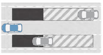
The design of the system is to detect vehicles that could have entered the blind spot zone. The detection area is on both sides of your vehicle, extending rearward from the exterior mirrors to approximately 13 ft (4 m) beyond the rear bumper. The detection area extends to approximately 59 ft (18 m) beyond the rear bumper when the vehicle speed is greater than 30 mph (48 km/h) to alert you of faster approaching vehicles.

Note: The system does not prevent contact with other vehicles. It does not detect parked vehicles, pedestrians, animals or other infrastructures.

Troubleshooting

..

Using the Blind Spot Information System

Vehicles with Automatic Transmission The system turns on when all of the following occur: You start your vehicle. You shift into drive (D). The vehicle speed is greater than 6 mph (10 km/h)...

Other information:

Lincoln Aviator 2020-2025 Service Manual: Diagnosis and Testing - Vehicle Dynamic Suspension - Vehicles With: Air Suspension


Diagnostic Trouble Code (DTC) Chart Diagnostics in this manual assume a certain skill level and knowledge of Ford-specific diagnostic practices. REFER to: Diagnostic Methods (100-00 General Information, Description and Operation).   Diagnostic Trouble Code Chart Module   DTC Description Action   SUMA B1041:52 Levelling Control: Not Activated   GO to Pinpoint Test W   SUMA C1043:00 Pressure Decrease Too Slow From Reservoir: No Sub Type Information   GO to Pinpoint Test M   SUMA C104C:11 Left Rear Spring Rate Valve: Circuit Short To Ground   GO to Pinpoint Test E   SUMA C104C:12 Left Rear Spring Rate Valve: Circuit Short To Battery   GO to Pinpoint Test E   SUMA C104C:13 Left Rear Spring Rate Valve: Circuit Open   GO to Pinpoint Test E   SUMA C104C:1A Left Rear Spring Rate Valve: Circuit Resistance Below Threshold   GO to Pinpoint Test E   SUMA C104C:1F Left Rear Spring Rate Valve: Circuit Intermittent   GO to Pinpoint Test E   SUMA C104D:11 Right Front Spring Rate Valve: Circuit Short To Ground   GO to Pinpoint Test D   SUMA C104D:12 Right Front Spring Rate Valve: Circuit Short To Battery   GO to Pinpoint Test D   SUMA C104D:13 Right Front Spring Rate Valve: Circuit Open   GO to Pinpoint Test D   SUMA C104D:1A Right Front Spring Rate Valve: Circuit Resistance Below Threshold   GO to Pinpoint Test D   SUMA C104D:1F Right Front Spring Rate Valve: Circuit Intermittent   GO to Pinpoint Test D   SUMA C104E:11 Right Rear Spring Rate Valve: Circuit Short To Ground   GO to Pinpoint Test F   SUMA C104E:12 Right Rear Spring Rate Valve: Circuit Short To Battery   GO to Pinpoint Test F   SUMA C104E:13 Right Rear Spring Rate Valve: Circuit Open   GO to Pinpoint Test F   SUMA C104E:1A Right Rear Spring Rate Valve: Circuit Resistance Below Threshold   GO to Pinpoint Test F   SUMA C104E:1F Right Rear Spring Rate Valve: Circuit Intermittent   GO to Pinpoint Test F   SUMA C104F:11 Left Front Spring Rate Valve: Circuit Short To Ground   GO to Pinpoint Test C   SUMA C104F:12 Left Front Spring Rate Valve: Circuit Short To Battery   GO to Pinpoint Test C   SUMA C104F:13 Left Front Spring Rate Valve: Circuit Open   GO to Pinpoint Test C   SUMA C104F:1A Left Front Spring Rate Valve: Circuit Resistance Below Threshold   GO to Pinpoint Test C   SUMA C104F:1F Left Front Spring Rate Valve: Circuit Intermittent   GO to Pinpoint Test C   SUMA C1124:07 Height Sensor(s): Mechanical Failures   GO to Pinpoint Test G   SUMA C1124:11 Height Sensor(s): Circuit Short To Ground   GO to Pinpoint Test H   SUMA C1124:12 Height Sensor(s): Circuit Short To Battery   GO to Pinpoint Test H   SUMA C1124:54 Height Sensor(s): Missing Calibration   GO to Pinpoint Test U   SUMA C1A03:2A Left Front Height Sensor: Stuck in Range   GO to Pinpoint Test I   SUMA C1A03:34 Left Front Height Sensor: Signal High Time Less Than Minimum   GO to Pinpoint Test I   SUMA C1A03:35 Left Front Height Sensor: Signal High Time Greater Than Maximum   GO to Pinpoint Test I   SUMA C1A03:36 Left Front Height Sensor: Signal Frequency Too Low   GO to Pinpoint Test I   SUMA C1A03:37 Left Front Height Sensor: Signal Frequency Too High   GO to Pinpoint Test I   SUMA C1A03:84 Left Front Height Sensor: Signal Below Allowable Range   GO to Pinpoint Test I   SUMA C1A03:85 Left Front Height Sensor: Signal Above Allowable Range   GO to Pinpoint Test I   SUMA C1A04:2A Right Front Height Sensor: Stuck in Range   GO to Pinpoint Test J   SUMA C1A04:34 Right Front Height Sensor: Signal High Time Less Than Minimum   GO to Pinpoint Test J   SUMA C1A04:35 Right Front Height Sensor: Signal High Time Greater Than Maximum   GO to Pinpoint Test J   SUMA C1A04:36 Right Front Height Sensor: Signal Frequency Too Low   GO to Pinpoint Test J   SUMA C1A04:37 Right Front Height Sensor: Signal Frequency Too High   GO to Pinpoint Test J   SUMA C1A04:84 Right Front Height Sensor: Signal Below Allowable Range   GO to Pinpoint Test J   SUMA C1A04:85 Right Front Height Sensor: Signal Above Allowable Range   GO to Pinpoint Test J   SUMA C1A05:2A Left Rear Height Sensor: Stuck in Range   GO to Pinpoint Test K   SUMA C1A05:34 Left Rear Height Sensor: Signal High Time Less Than Minimum   GO to Pinpoint Test K   SUMA C1A05:35 Left Rear Height Sensor: Signal High Time Greater Than Maximum   GO to Pinpoint Test K   SUMA C1A05:36 Left Rear Height Sensor: Signal Frequency Too Low   GO to Pinpoint Test K   SUMA C1A05:37 Left Rear Height Sensor: Signal Frequency Too High   GO to Pinpoint Test K   SUMA C1A05:84 Left Rear Height Sensor: Signal Below Allowable Range   GO to Pinpoint Test K   SUMA C1A05:85 Left Rear Height Sensor: Signal Above Allowable Range   GO to Pinpoint Test K   SUMA C1A06:2A Right Rear Height Sensor: Stuck in Range   GO to Pinpoint Test L   SUMA C1A06:34 Right Rear Height Sensor: Signal High Time Less Than Minimum   GO to Pinpoint Test L   SUMA C1A06:35 Right Rear Height Sensor: Signal High Time Greater Than Maximum   GO to Pinpoint Test L   SUMA C1A06:36 Right Rear Height Sensor: Signal Frequency Too Low   GO to Pinpoint Test L   SUMA C1A06:37 Right Rear Height Sensor: Signal Frequency Too High   GO to Pinpoint Test L   SUMA C1A06:84 Right Rear Height Sensor: Signal Below Allowable Range   GO to Pinpoint Test L   SUMA C1A06:85 Right Rear Height Sensor: Signal Above Allowable Range   GO to Pinpoint Test L   SUMA C1A20:00 Pressure Increase Too Slow When Filling Reservoir: No Sub Type Information   GO to Pinpoint Test M   SUMA C1A27:09 Compressor: Component Failures   GO to Pinpoint Test N   SUMA C1A27:63 Compressor: Circuit/Component Protection Time-Out   GO to Pinpoint Test N   SUMA C1A27:98 Compressor: Component Or System Over Temperature   GO to Pinpoint Test N   SUMA C1A27:99 Compressor: Exceeded Learning Limit   GO to Pinpoint Test N   SUMA C1A31:63 Left Front Corner Valve: Circuit/Component Protection Time-Out   GO to Pinpoint Test AD   SUMA C1A32:63 Right Front Corner Valve: Circuit/Component Protection Time-Out   GO to Pinpoint Test AD   SUMA C1A33:63 Left Rear Corner Valve: Circuit/Component Protection Time-Out   GO to Pinpoint Test AD   SUMA C1A34:63 Right Rear Corner Valve: Circuit/Component Protection Time-Out   GO to Pinpoint Test AD   SUMA C1A36:63 Exhaust Valve: Circuit/Component Protection Time-Out   GO to Pinpoint Test AD   SUMA U0100:87 Lost Communication With ECM / PCM: Missing Message   GO to Pinpoint Test O   SUMA U0121:87 Lost Communication With Anti-Lock Brake System (ABS) Control Module: Missing Message   GO to Pinpoint Test P   SUMA U0122:87 Lost Communication With Vehicle Dynamics Control Module: Missing Message   GO to Pinpoint Test Q   SUMA U0131:87 Lost Communication With Power Steering Control Module "A": Missing Message   GO to Pinpoint Test R   SUMA U0140:87 Lost Communication With Body Control Module: Missing Message   GO to Pinpoint Test S   SUMA U0146:87 Lost Communication With Serial Data Gateway "A": Missing Message   GO to Pinpoint Test T   SUMA U0401:00 Invalid Data Received from ECM/PCM A: No Sub Type Information   GO to Pinpoint Test X   SUMA U0415:00 Invalid Data Received from Anti-Lock Brake System (ABS) Control Module "A": No Sub Type Information   GO to Pinpoint Test Y   SUMA U0416:00 Invalid Data Received From Vehicle Dynamics Control Module: No Sub Type Information   GO to Pinpoint Test Z   SUMA U0420:00 Invalid Data Received from Power Steering Control Module "A": No Sub Type Information   GO to Pinpoint Test AA   SUMA U0422:00 Invalid Data Received From Body Control Module: No Sub Type Information   GO to Pinpoint Test AB   SUMA U0447:00 Invalid Data Received From Serial Data Gateway "A": No Sub Type Information   GO to Pinpoint Test AC   SUMA U2100:00 Initial Configuration Not Complete: No Sub Type Information   GO to Pinpoint Test V   SUMA U2100:56 Initial Configuration Not Complete: Invalid/Incompatible Configuration   GO to Pinpoint Test V   SUMA U3000:04 Control Module: System Internal Failures   GO to Pinpoint Test V   SUMA U3000:45 Control Module: Program Memory Failure   GO to Pinpoint Test V   SUMA U3000:46 Control Module: Calibration/Parameter Memory Failure   GO to Pinpoint Test V   SUMA U3000:47 Control Module: Watchdog/Safety µC Failure   GO to Pinpoint Test V   SUMA U3000:48 Control Module: Supervision Software Failure   GO to Pinpoint Test V   SUMA U3003:16 Battery Voltage: Circuit Voltage Below Threshold   GO to Pinpoint Test A   SUMA U3003:17 Battery Voltage: Circuit Voltage Above Threshold   GO to Pinpoint Test B Symptom Chart Symptom Chart: Vehicle Dynamic Suspension Diagnostics in this manual assume a certain skill level and knowledge of Ford-specific diagnostic practices...

Lincoln Aviator 2020-2025 Service Manual: Diagnosis and Testing - Roof Opening Panel


DTC Chart: Roof Opening Panel Diagnostics in this manual assume a certain skill level and knowledge of Ford-specific diagnostic practices. REFER to: Diagnostic Methods (100-00 General Information, Description and Operation).   BCM Module DTC Chart DTC Description Action B12F4:12 Vehicle Speed Output: Circuit Short To Battery   GO to Pinpoint Test A B12F4:14 Vehicle Speed Output: Circuit Short To Ground or Open   GO to Pinpoint Test A - All other BCM Diagnostic Trouble Codes (DTCs)   REFER to: Body Control Module (BCM) (419-10 Multifunction Electronic Modules, Diagnosis and Testing)...

Categories

Remote Control

Passive Key

Lincoln Aviator. Remote Control

The passive key operates the power locks and the remote start system. The passive key must be in your vehicle to use the push button start.

Note: You may not be able to shift out of park (P) unless the passive key is inside your vehicle.

read more

 
Copyright © 2025 www.liaviator2.com