Lincoln Aviator: Engine - 3.0L EcoBoost / Removal - Engine
Special Tool(s) /
General Equipment
.jpg) |
100-001
(T50T-100-A)
Slide Hammer |
.jpg) |
204-592
Separator, Lower Arm Ball Joint
TKIT-2006C-FFMFLM
TKIT-2006C-LM
TKIT-2006C-ROW |
 |
205-832
Remover, Halfshaft
TKIT-2006C-FFMFLM
TKIT-2006C-LM
TKIT-2006C-ROW |
.jpg) |
303-1246
Engine Spreader Bar
TKIT-2006UF-FLM
TKIT-2006UF-ROW |
.jpg) |
303-1634
Lift Eyes (2)
TKIT-2014D-ROW3
TKIT-2014D-FL_ROW |
| Tie Rod End Remover |
| Adjustable Mounting Arm |
| Cable Ties |
| Powertrain Jack |
| Wooden Block |
Materials
| Name |
Specification |
Motorcraft® Metal Brake Parts Cleaner
PM-4-A, PM-4-B |
-
|
NOTICE:
The turbocharger compressor vanes can be damaged by even the
smallest particles. When removing any turbocharger or engine air intake
system component, ensure that no debris enters the system. Failure to do
so may result in damage to the turbocharger.
LHD AWD/LHD RWD
-
With the vehicle in NEUTRAL, position it on a hoist.
Refer to: Jacking and Lifting (100-02 Jacking and Lifting, Description and Operation).
-
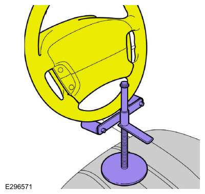
Using a holding device, hold the steering wheel.
-
Release the fuel system pressure.
Refer to: Fuel System Pressure Release (310-00A Fuel System - General Information - 3.0L EcoBoost, General Procedures).
-
Disconnect the battery ground.
Refer to: Battery Disconnect and Connect (414-01 Battery, Mounting and Cables, General Procedures).
-
Drain the cooling system.
Refer to: Engine Cooling System Draining, Vacuum Filling and Bleeding (303-03A Engine Cooling - 3.0L EcoBoost, General Procedures).
-
Recover the A/C system.
Refer to: Air Conditioning (A/C) System Recovery, Evacuation and Charging - Vehicles With: R1234YF Refrigerant (412-00 Climate Control System - General Information, General Procedures).
-
Remove the retainers and the RH engine compartment cover.
-
Remove the retainers and the LH engine compartment cover.
-
Remove the retainers and the upper radiator panel.
-
Using cable ties or mechanics wire through the upper location holes, to support the cooling module.
Use the General Equipment: Cable Ties
-
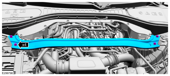
Remove the bolts and the suspension support bar.
-
Remove the engine oil filter and drain the engine oil.
Refer to: Engine Oil Draining and Filling (303-01A Engine - 3.0L EcoBoost, General Procedures).
-
Remove the following items:
-
Refer to: Cowl Panel (501-02 Front End Body Panels, Removal and Installation).
-
Refer to: Degas Bottle (303-03A Engine Cooling - 3.0L EcoBoost, Removal and Installation).
-
Refer to: Air Cleaner (303-12 Intake Air Distribution and Filtering - 3.0L EcoBoost/3.0L EcoBoost – Hybrid (BQ), Removal and Installation).
-
Refer to: Charge Air Cooler (CAC) Outlet Pipe (303-12 Intake Air Distribution and Filtering - 3.0L EcoBoost/3.0L EcoBoost – Hybrid (BQ), Removal and Installation).
-
LH side.
Refer to: Charge Air Cooler (CAC) Intake Pipe (303-12 Intake Air Distribution and Filtering - 3.0L EcoBoost/3.0L EcoBoost – Hybrid (BQ), Removal and Installation).
-
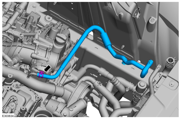
Release the clamp and remove the coolant hose.
-
-
Depress the raised area of the pipe.
-
Remove the air cleaner inlet pipe.
-
-
Loosen the clamp and remove the air cleaner outlet pipe.
-
Loosen the clamps and remove the CAC inlet pipe.
-
Release the clamp and disconnect the lower radiator hose.
-
Loosen the clamp and disconnect the upper radiator hose.
-
Position the hoses aside.
-
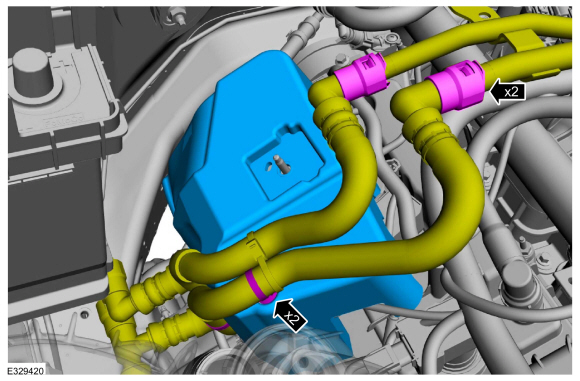
Release the clamp and disconnect the coolant hose.
-
Disconnect the coolant hose quick release coupling.
-
Position the hoses aside.
-
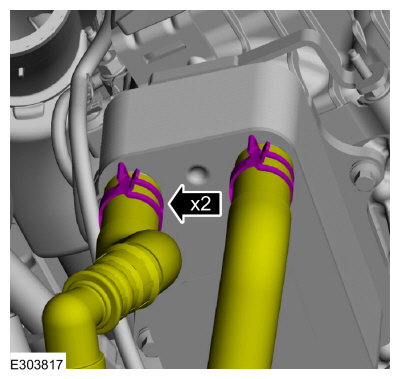
Release the clamps and disconnect the oil cooler hoses.
-
Position the hoses aside.
-
Remove the bolt and detach the wiring harness retainer.
-
Position the ground cable aside.
-
Remove the generator.
Refer to: Generator - 3.0L EcoBoost (414-02 Generator and Regulator, Removal and Installation).
-
-
If equipped, disconnect the block heater electrical connector.
-
Detach the wiring harness retainer.
-
-
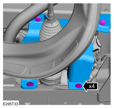
Remove the bolt and disconnect the steering shaft.
-
-
Disconnect the center PCM electrical connector and wiring harness retainer.
-
Disconnect the engine harness electrical connector,
retainer and position the engine wiring harness on the engine.
-
-
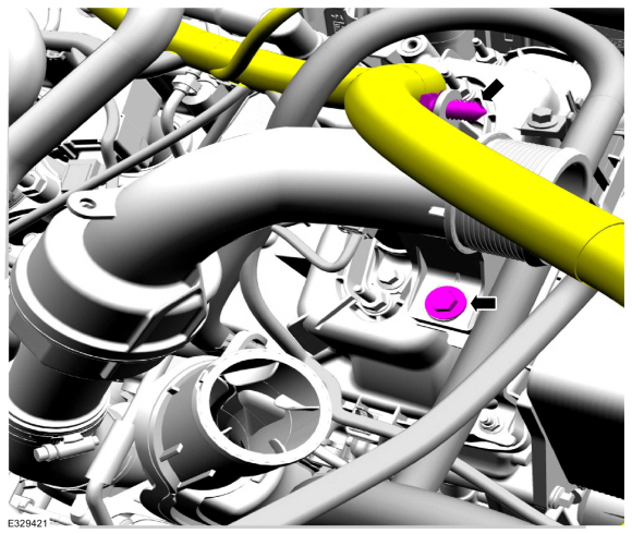
Release the clamp and disconnect the heater hose.
-
Remove the bolts and position the heater hose brackets aside.
-
Remove the bolts and the intake manifold bracket.
-
NOTE:
When removing or installing the fuel injection pump
noise insulator, spreading the openings will reduce the risk of damage.
-
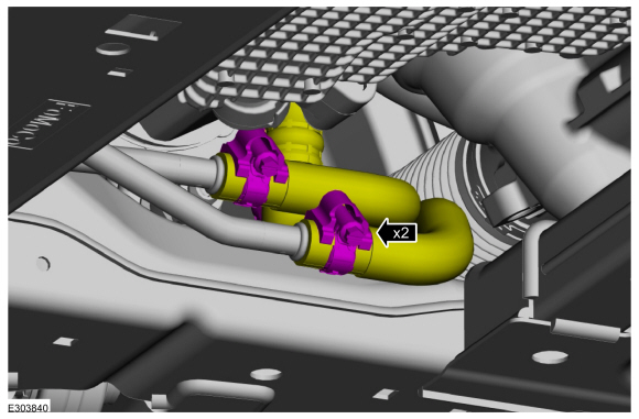
Disconnect the coolant hoses.
-
Detach the coolant hose retainers.
-
Remove the fuel injection pump noise insulator.
-
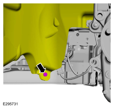
-
Remove the bolt.
-
Detach the wiring harness retainer.
-
Remove the nuts, the bolt and position the high-pressure fuel pump shield aside.
-
-
Disconnect the high-pressure fuel pump fuel feed spring lock coupling.
Refer to: Spring Lock Couplings (310-00A Fuel System - General Information - 3.0L EcoBoost, General Procedures).
-
Remove the high-pressure fuel pump shield.
-
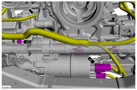
Remove the bolt and position the ground cable aside.
-
Remove the wiring harness bracket bolt.
-
Detach the wiring harness retainers.
-
-
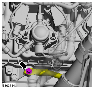
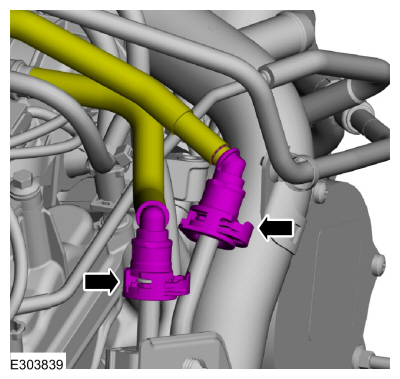
Disconnect the fuel supply tube quick release coupling.
Refer to: Quick Release Coupling (310-00A Fuel System - General Information - 3.0L EcoBoost, General Procedures).
-
Disconnect the EVAP supply tube quick release coupling.
Refer to: Quick Release Coupling (310-00A Fuel System - General Information - 3.0L EcoBoost, General Procedures).
-
If equipped, remove the front suspension height sensors.
Refer to: Front Suspension Height Sensor (204-05 Vehicle Dynamic Suspension, Removal and Installation).
-
-
Disconnect the A/C wiring harness electrical connectors.
-
Detach the wiring harness retainer.
-
Remove the nuts and disconnect the A/C lines from A/C compressor.
-
Make sure that all openings are sealed.
-
Remove the pin-type retainers and the steering shield from the LH subframe.
-
Remove the splash shield pin-type retainer from the LH subframe and position aside.
-
NOTE:
If equipped with AWD.
-
Disconnect the vent hose.
-
Disconnect the wiring harness electrical connector.
-
Loosen the clamps and disconnect the coolant hoses.
-
Remove the coolant tube bracket bolt.
-
NOTE:
Be prepared to collect escaping fluid.
Remove the bolt, the nuts and the transmission fluid cooler.
-
If equipped, detach the air suspension tube retainers.
-
Remove the steering shield pin-type retainers from the RH subframe.
-
Remove the pin-type retainers and the steering shield from the RH subframe.
-
Remove the splash shield pin-type retainer from the RH subframe.
-
NOTE:
If equipped with AWD.
Disconnect the wiring harness electrical connector from the RH transfer case.
-
Detach the wiring harness retainer.
-
-
If equipped, disconnect the RH transfer case vent hose.
-
Disconnect the steering gear wiring harness
electrical connectors, wiring harness retainers and position the harness
to the RH side of vehicle.
-
NOTICE:
Use the internal or external hex-holding feature to
prevent the ball and stud from turning while removing or installing the
stabilizer bar link nuts. The link boot seal must not be allowed to
twist while tightening the link nuts or damage to the boot seal will
occur.
NOTE:
On both sides.
Remove and discard the nut and position the sway bar link aside.
LHD RWD
-
NOTICE:
Do not use a hammer to separate the outer tie-rod
end from the wheel knuckle or damage to the wheel knuckle may result.
NOTICE:
Use care when installing the tie rod separator or damage to the outer tie-rod end boot may occur.
NOTE:
On both sides.
-
Remove and discard the tie rod end nut.
-
Separate the tie rod end from the wheel knuckle.
Use the General Equipment: Tie Rod End Remover
-
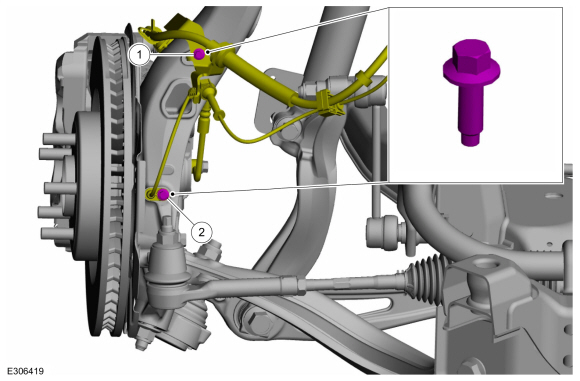
NOTE:
On both sides.
-
Remove the retainer bracket bolt.
-
Remove the bolt and the front wheel speed sensor.
-
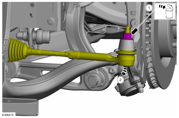
NOTICE:
Do not use power tools to remove or install the
lower arm outboard nut. Damage to the ball joint or ball joint seal may
occur.
NOTE:
Use the TORX PLUS® holding feature to prevent the
ball stud from turning while removing or installing the lower arm
outboard nut. Torx® and TORX PLUS® is a reg. tm of Acument Intellectual
Properties, LLC.
NOTE:
On both sides.
Remove and discard the front lower arm outboard nut.
-
NOTICE:
Do not use a hammer, prying device, or separator
fork to separate the ball joint from the wheel knuckle. Damage to the
ball joint or ball joint seal may occur.
NOTICE:
Use care when releasing the lower arm and wheel
knuckle into the resting position. Damage to the ball joint or ball
joint seal may occur.
NOTE:
On both sides.
Separate the front lower arm from the wheel Knuckle.
Use Special Service Tool: 204-592
Separator, Lower Arm Ball Joint.
-
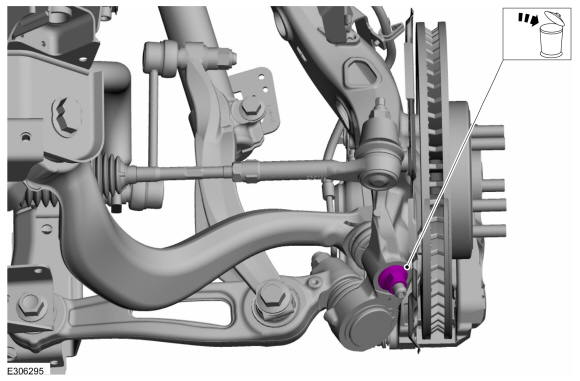
NOTE:
On both sides.
-
Remove and discard the lower arm bracket bolt and nut.
-
NOTICE:
Do not use power tools to remove or install the
lower arm outboard nut. Damage to the ball joint or ball joint seal may
occur.
NOTE:
Use the TORX PLUS® holding feature to prevent
the ball stud from turning while removing or installing the lower arm
outboard nut. Torx® and TORX PLUS® is a reg. tm of Acument Intellectual
Properties, LLC.
Remove and discard the rear lower arm outboard nut.
-
NOTICE:
Do not use a hammer, prying device, or separator
fork to separate the lower arm from the ball joint. Damage to the ball
joint or ball joint seal may occur.
NOTICE:
Use care when releasing the lower arm and wheel
knuckle into the resting position. Damage to the ball joint or ball
joint seal may occur.
NOTE:
On both sides.
Separate the rear lower arm from the wheel Knuckle.
Use Special Service Tool: 204-592
Separator, Lower Arm Ball Joint.
LHD AWD
-
Remove the RH and LH halfshafts.
Refer to: Halfshaft (205-04 Front Drive Halfshafts, Removal and Installation).
LHD AWD/LHD RWD
-
Remove the following items:
-
Refer to: Transmission - 3.0L EcoBoost (307-01A Automatic Transmission - 10-Speed Automatic Transmission – 10R60, Removal and Installation).
-
RH side.
Refer to: Exhaust Flexible Pipe (309-00A Exhaust System - 3.0L EcoBoost, Removal and Installation).
-
Detach the retainer and remove the vent hose(s).
-
NOTE:
AWD shown, RWD similar.
Detach the HO2S wiring harness retainers from the LH subframe.
-
NOTE:
AWD shown, RWD similar.
-
Disconnect the HO2S and catalyst monitor sensor electrical connectors.
-
Detach the wiring harness retainers.
-
NOTICE:
Only use hand tools when removing the engine mount nuts or damage to the engine mount can occur.
-
Remove the LH engine mount nut.
-
Discard the engine mount nut.
-
NOTICE:
Only use hand tools when removing the engine mount nuts or damage to the engine mount can occur.
-
Remove the RH engine mount nut.
-
Discard the engine mount nut.
-
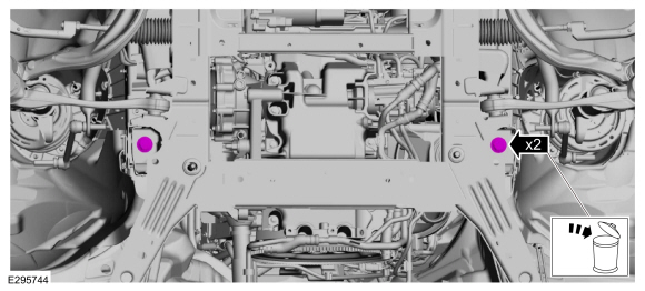
Remove the bolt and position the RH underbody shield aside.
-
-
Remove the middle subframe bolts.
-
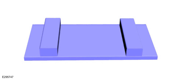
Position two boards onto the powertrain jack as shown.
-
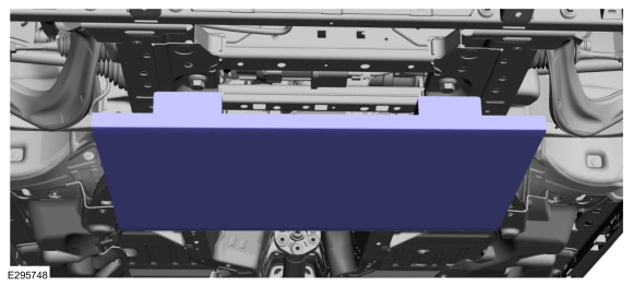
Position the powertrain jack and blocks of wood under the powertrain and subframe .
Use the General Equipment: Powertrain Jack
Use the General Equipment: Wooden Block
-
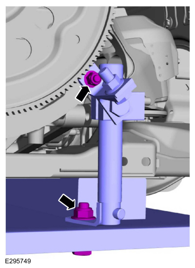
Install, adjust and tighten the adjustable mounting arm.
Use the General Equipment: Adjustable Mounting Arm
-
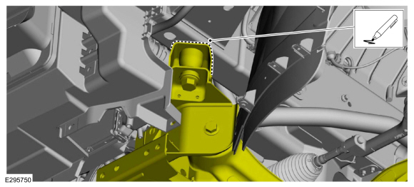
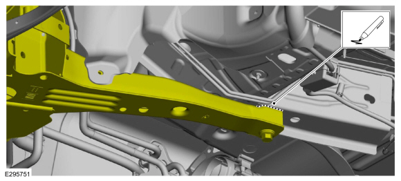
Mark the front subframe location.
-
Mark the rear subframe location.
-
Remove the front radiator support bar bolts.
-
-
Remove the front subframe bolts.
-
-
Remove the rear subframe bolts.
-
-
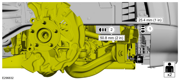
With the aid of an assistant and using the
powertrain jack, lower the powertrain and subframe 25.4 mm (1 in).
-
With the aid of an assistant and using the
powertrain jack, position the powertrain and subframe rearwards 50.8 mm
(2 in).
-
With the aid of an assistant and using the powertrain jack, lower the powertrain and subframe as an assembly.
-
NOTE:
AWD shown, RWD similar.
-
Remove the nuts and the RH catalytic converter.
-
-
Remove and discard the gasket.
-
If damaged, remove and discard the studs.
LHD AWD
-
Remove the fasteners and the heat shield.
-
Using the special tools, remove the front drive shaft.
Use Special Service Tool: 100-001
(T50T-100-A)
Slide Hammer.
, 205-832
Remover, Halfshaft.
-
Remove and discard the front axle pinion stem circlip.
-
Remove and discard the front axle pinion stem O-ring.
LHD AWD/LHD RWD
-
Remove the bolt and the bracket.
-
Remove the fasteners.
-
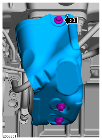
Remove the bolts and the heat shield.
-
-
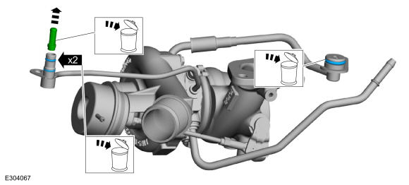
Remove the TC coolant supply tube bolt.
-
Release the clamp and disconnect the TC coolant return hose.
-
-
Remove the TC oil supply tube bolt.
-
Release the clamp and disconnect the vacuum hose.
-
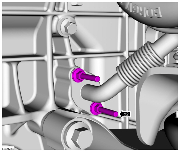
Remove the fasteners and the TC.
-
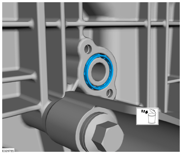
Remove and discard the TC oil return tube tube-to-engine block gasket.
-
-
Remove and discard the TC oil supply tube filter and O-ring seals.
-
Remove and discard the TC coolant supply tube O-ring seal.
-
NOTICE:
Inspect the turbocharger tubes and the sealing
surfaces. Ensure that the retaining brackets are not bent, check for
square-ness of the retaining brackets to the O-ring areas. Use brake
cleaner and a NYLON brush to clean. DO NOT USE A METAL BRUSH; DAMAGE TO
SEALING AREA WILL RESULT IN LEAKS.
-
Clean and inspect the TC oil supply tube.
Material: Motorcraft® Metal Brake Parts Cleaner
/ PM-4-A, PM-4-B
-
Clean and inspect the TC oil return tube.
Material: Motorcraft® Metal Brake Parts Cleaner
/ PM-4-A, PM-4-B
-
Clean and inspect the TC coolant supply tube.
Material: Motorcraft® Metal Brake Parts Cleaner
/ PM-4-A, PM-4-B
-
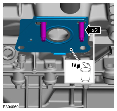
-
Remove and discard the TC gasket.
-
If damaged, remove and discard the TC stud(s).
-
Install Special Service Tool: 303-1634
Lift Eyes (2).
-
Install Special Service Tool: 303-1634
Lift Eyes (2).
-
Install commercially available quick links to the spreader bar and lift eyes.
Install Special Service Tool: 303-1246
Engine Spreader Bar.
-
Install the floor crane and chain,.
-
Remove.
Use the General Equipment: Adjustable Mounting Arm
-
NOTE:
AWD shown, RWD similar.
Using the floor crane, remove the engine from subframe.
Special Tool(s) /
General Equipment
303-1248Camshaft holding toolsTKIT-2006UF-FLMTKIT-2006UF-ROW
303-1696Camshaft holding fixture
Removal
NOTICE:
During engine repair procedures, cleanliness is extremely
important...
Special Tool(s) /
General Equipment
205-153
(T80T-4000-W)
Handle
303-1246Engine Spreader BarTKIT-2006UF-FLMTKIT-2006UF-ROW
303-1247VCT Spark Plug Tube Seal Remover and InstallerTKIT-2006UF-FLMTKIT-2006UF-ROW
303-1634Lift Eyes (2)TKIT-2014D-ROW3TKIT-2014D-FL_ROW
303-409
(T92C-6700-CH)
Remover, Crankshaft SealTKIT-1992-FH/FMH/FLMHTKIT-1993-LMH/MH
Floor Crane
Mounting Stand
Plastic Scraper
Flat-Bladed Screwdriver
Materials
Name
Specification
Motorcraft® Silicone Gasket RemoverZC-30-A
-
Motorcraft® Metal Surface Prep WipesZC-31-B
-
Motorcraft® Metal Brake Parts CleanerPM-4-A, PM-4-B
-
NOTICE:
During engine repair procedures, cleanliness is extremely
important...
Other information:
Special Tool(s) /
General Equipment
Wooden Block
DISASSEMBLY
NOTICE:
Failure to follow the instructions below may result in damage to the TPMS.
NOTICE:
The TPMS
sensor is mounted to the valve stem. Removal of the valve stem requires
dismounting the tire from the wheel and removal of the TPMS sensor...
Removal
NOTE:
Removal steps in this procedure may contain installation details.
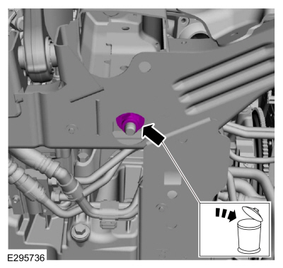
Remove the EVAP canister vent solenoid.
Refer to: Evaporative Emission Canister Vent Solenoid (303-13A Evaporative Emissions - 3.0L EcoBoost, Removal and Installation)...
.jpg)
.jpg)
.jpg)
.jpg)
.jpg)
.jpg)
.jpg)
.jpg)
.jpg)
.jpg)
.jpg)
.jpg)
.jpg)
.jpg)
.jpg)
.jpg)
.jpg)
.jpg)
.jpg)
.jpg)
.jpg)
.jpg)
.jpg)
.jpg)
.jpg)
.jpg)
.jpg)
.jpg)
.jpg)
.jpg)
.jpg)
.jpg)
.jpg)
.jpg)
.jpg)
.jpg)
.jpg)
.jpg)
.jpg)
.jpg)
.jpg)
.jpg)
.jpg)
.jpg)
.jpg)
.jpg)
.jpg)
.jpg)
.jpg)
.jpg)
.jpg)
.jpg)
.jpg)
.jpg)
.jpg)
.jpg)
 Removal and Installation - Variable Camshaft Timing (VCT) Unit
 Removal - Engine Block Skirt Stiffener