
Lincoln Aviator 2020-2026 Owners Manual / Data Privacy / Settings Data
Lincoln Aviator: Data Privacy / Settings Data
Your vehicle has electronic control units that have the ability to store data based on your personalized settings. The data is stored locally in the vehicle or on devices that you connect to it, for example, a USB drive or digital music player. You can delete some of this data and also choose whether to share it through the services to which you subscribe.
Comfort and Convenience Data
Data recorded includes, for example:
- Seat and steering wheel position.
- Climate control settings.
- Radio presets.
Entertainment Data
Data recorded includes, for example:
- Music, videos or album art.
- Contacts and corresponding address book entries.
- Navigation destinations.
 Event Data
This vehicle is equipped with an event data
recorder. The main purpose of an event data
recorder is to record, in certain crash or near
crash-like situations, such as an airbag
deployment or hitting a road obstacle; this
data will assist in understanding how a
vehicle’s systems performed...
 Connected Vehicle Data
The modem has a SIM. The
modem was enabled when your
vehicle was built and periodically
sends messages to stay connected to the
cell phone network, receive automatic
software updates and send vehicle-related
information to us, for example diagnostic
information...
Other information:
Lincoln Aviator 2020-2026 Service Manual: Description and Operation - Wipers and Washers - System Operation and Component Description
System Operation System Diagram Item Description 1 Wiper/Washer Switch 2 Rain Sensor 3 Washer Motor 4 SCCM 5 Windshield Wiper Motor 6 GWMGWM 7 BCM 8 IPC 9 PCM 10 BCMC 11 Wiper Relay 12 BCMC 13 Rear Window Washer Relay 14 Rear Wiper Motor Network Message Chart SCCM Network Input Messages Broadcast Message Originating Module Message Purpose Vehicle speed PCM The SCCM uses vehicle speed information for operation of the speed sensitive wiper function...
Lincoln Aviator 2020-2026 Owners Manual: Body Control Module
Argentina Brazil Ghana Jamaica Moldova Morocco Paraguay 2019-01-I-000076 Serbia Singapore South Africa Ukraine United Arab Emirates (U.A.E.) United States and Canada WARNING: Changes or modifications not expressively approved by the party responsible for compliance could void the user's authority to operate the equipment...
Categories
- Manuals Home
- Lincoln Aviator Owners Manual
- Lincoln Aviator Service Manual
- Opening and Closing the Hood
- Fuel Quality
- Configuring The Head Up Display
- New on site
- Most important about car
Fastening the Seatbelts
The front outboard and rear safety restraints in the vehicle are combination lap and shoulder belts.
Insert the belt tongue into the proper buckle (the buckle closest to the direction the tongue is coming from) until you hear a snap and feel it latch. Make sure that you securely fasten the tongue in the buckle.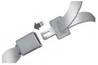

Copyright © 2026 www.liaviator2.com