Lincoln Aviator 2020-2026 Owners Manual / Vehicle Identification
Lincoln Aviator: Vehicle Identification
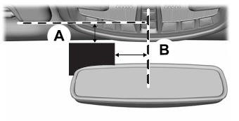
Install any devices that use radio frequency identification, for example, toll readers or vehicle identification cards, to the specified area on the windshield.
Note: Follow the manufacturer’s installation instructions.
Note: When installing the radio frequency identification device, do not block objects such as the rain sensor and the auto-dimming sensor.


Other information:
Lincoln Aviator 2020-2026 Owners Manual: Information on T Type Tires
T145/80D16 is an example of a tire size. Note: The temporary tire size for your vehicle may be different from this example. Tire Quality Grades do not apply to this type of tire. T type tires have some additional information beyond those of P type tires; these differences are described below: T: Indicates a type of tire, designated by the Tire and Rim Association, that is intended for temporary service on cars, sport utility vehicles, minivans and light trucks...
Lincoln Aviator 2020-2026 Owners Manual: Audio and Voice Control
Audio Control You can operate the following functions with the control: Move the selector switch up to increase volume level. Move the selector switch down to decrease volume level. Move the selector switch to the left to access the previous media selection...
Categories
- Manuals Home
- Lincoln Aviator Owners Manual
- Lincoln Aviator Service Manual
- Description and Operation - Jacking and Lifting
- USB Port and Power Point Locations
- Changing the Front Wiper Blades - Vehicles With: Heated Wiper Blades
- New on site
- Most important about car
Adjusting the Steering Wheel - Vehicles With: Manual Adjustable Steering Column
WARNING: Do not adjust the steering wheel when your vehicle is moving.
Note: Make sure that you are sitting in the correct position.
Unlock the steering column. Adjust the steering wheel to the desired position.
Copyright © 2026 www.liaviator2.com