
Lincoln Aviator: Unique Driving Characteristics / Auto-Start-Stop - Excluding: Plug-In Hybrid Electric Vehicle (PHEV)
The system helps reduce fuel consumption by automatically stopping and restarting the engine when your vehicle has stopped. The engine restarts automatically when you release the brake pedal.
In some situations, your vehicle may restart automatically, for example:
- To maintain interior comfort.
- To recharge the battery.
Note: Power assist steering turns off when the engine is off.
Note: If your vehicle is flex fuel capable, Auto-Start-Stop will be inhibited for a short time after a refuel event while the system is verifying the fuel type being used.
WARNING: Apply the parking brake, shift into park (P), switch the ignition off and remove the key before you leave your vehicle. Failure to follow this instruction could result in personal injury or death.
WARNING: Apply the parking brake, shift into park (P), switch the ignition off and remove the key before you open the hood or have any service or repair work completed. If you do not switch the ignition off, the engine could restart at any time. Failure to follow this instruction could result in personal injury or death.
WARNING: The system may require the engine to automatically restart when the auto-start-stop indicator illuminates green or flashes amber. Failure to follow this instruction could result in personal injury.
The Auto-Start-Stop system status is available at a glance within the information display.

 Enabling Auto-Start-Stop
The system automatically enables every time
you start your vehicle if:
Your vehicle exceeds an initial speed of
3 mph (5 km/h) after you have initially
started your vehicle...
Other information:
Lincoln Aviator 2020-2026 Service Manual: Removal and Installation - Steering Column Lower Shaft
Removal NOTE: Removal steps in this procedure may contain installation details. NOTICE: Do not allow the steering column to rotate while the steering column shaft is disconnected or damage to the steering column internal sensor may result...
Lincoln Aviator 2020-2026 Service Manual: General Procedures - Fixed Glass
Special Tool(s) / General Equipment Power Caulk Gun Power Fixed Glass Removal Tool Cold Knife Knife Vacuum Cleaner Materials Name Specification Sika® SikaTack® MACH 60 / Sika® SikaTack® MACH 30 / Dow® BETASEAL™ Express - Sika Tack ASAP Urethane Adhesive - Motorcraft® Ultra-Clear Spray Glass CleanerZC-23 ESR-M14P5-A Sika Tack® MOVE...
Categories
- Manuals Home
- Lincoln Aviator Owners Manual
- Lincoln Aviator Service Manual
- Garage Door Opener
- Resetting the System
- Drive Modes
- New on site
- Most important about car
Child Seats
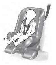
Use a child restraint (sometimes called an infant carrier, convertible seat, or toddler seat) for infants, toddlers and children weighing 40 lb (18 kg) or less (generally four-years-old or younger).
Using Lap and Shoulder Belts
WARNING: Do not place a rearward facing child restraint in front of an active airbag. Failure to follow this instruction could result in personal injury or death.
