Lincoln Aviator 2020-2024 Service Manual / Electrical / Battery and Charging System / High Voltage Battery Charging System / Removal and Installation - Secondary On-Board Diagnostic Control Module A (SOBDM) - Plug-In Hybrid Electric Vehicle (PHEV)

Lincoln Aviator: High Voltage Battery Charging System / Removal and Installation - Secondary On-Board Diagnostic Control Module A (SOBDM) - Plug-In Hybrid Electric Vehicle (PHEV)

Special Tool(s) / General Equipment

Hose Clamp(s)

Removal

  1.   WARNING: Before beginning any service procedure in this section, refer to Safety Warnings in section 100-00 General Information. Failure to follow this instruction may result in serious personal injury.

    Refer to: Health and Safety Precautions (100-00 General Information, Description and Operation).
  1. NOTE: If installing a new module, it is necessary to upload the module configuration information to the scan tool prior to removing the module. This information must be downloaded into the new module after installation.

    Upload the SOBDM configuration to the diagnostic scan tool by following the diagnostic scan tool on-screen instructions.
  1. De-energize the high voltage system.
    Refer to: High Voltage System De-energizing (414-03A High Voltage Battery, Mounting and Cables, General Procedures).
  1. Remove the LH headlight assembly.
    Refer to: Headlamp Assembly (417-01 Exterior Lighting, Removal and Installation).
  1. Remove the air cleaner assembly.
    Refer to: Air Cleaner (303-12 Intake Air Distribution and Filtering - 3.0L EcoBoost/3.0L EcoBoost – Hybrid (BQ), Removal and Installation).
  1. Remove the LH side fender splash shield.
    Refer to: Fender Splash Shield (501-02 Front End Body Panels, Removal and Installation).
  1. Disconnect the wire retainer from the degas bottle.
  1. Remove the bolt and position aside the degas bottle.
    Torque: 44 lb.in (5 Nm)
  1. Remove the CAC outlet pipe.
    Refer to: Charge Air Cooler (CAC) Outlet Pipe (303-12 Intake Air Distribution and Filtering - 3.0L EcoBoost/3.0L EcoBoost – Hybrid (BQ), Removal and Installation).
  1. Disconnect the electrical connector.
  1. Disconnect the electrical connectors and position aside the wire harness.
  1. Disconnect and position aside the coolant hose.
    Use the General Equipment: Hose Clamp(s)
    • Disconnect the coolant hose.
      Use the General Equipment: Hose Clamp(s)
    • Release the clip and position aside the coolant hose.
  1. Remove the bolts.
    Torque: 26 lb.ft (35 Nm)
  1. Remove the bolts and the SOBDM.
    Torque: 26 lb.ft (35 Nm)

Installation

  1. To install, reverse the removal procedure.
  1. If a new module is installed, download the SOBDM configuration information from the diagnostic scan tool to the new SOBDM following the diagnostic scan tool on-screen instructions.
  1. Bleed the cooling system.
    Refer to: Cooling System Filling and Bleeding (303-03C Electric Powertrain Cooling - 3.0L EcoBoost – Hybrid (BQ), General Procedures).

    Removal and Installation - Charge Port - Plug-In Hybrid Electric Vehicle (PHEV)

    Removal NOTE: Removal steps in this procedure may contain installation details.   WARNING: Before beginning any service procedure in this section, refer to Safety Warnings in section 100-00 General Information...

    Removal and Installation - Charge Status Indicator (CSI) - Plug-In Hybrid Electric Vehicle (PHEV)

    Removal   WARNING: Before beginning any service procedure in this section, refer to Safety Warnings in section 100-00 General Information...

    Other information:

    Lincoln Aviator 2020-2024 Service Manual: Removal and Installation - Air Inlet Door Actuator


    Removal Remove the climate control housing. Refer to: Climate Control Housing (412-00 Climate Control System - General Information, Removal and Installation). Remove the screws and the air inlet door actuator. Disconnect the electrical connector...

    Lincoln Aviator 2020-2024 Service Manual: Diagnosis and Testing - Parking Aid


    Diagnostic Trouble Code (DTC) Chart Diagnostics in this manual assume a certain skill level and knowledge of Ford-specific diagnostic practices. REFER to: Diagnostic Methods (100-00 General Information, Description and Operation).   Diagnostic Trouble Code Chart Module   DTC Description Action   APIM C1001:01 Vision System Camera:General Electrical Failure   GO to Pinpoint Test A   APIM C1001:01 Vision System Camera:General Electrical Failure   GO to Pinpoint Test J   APIM C1001:02 Vision System Camera:General Signal Failure   GO to Pinpoint Test A   APIM C1001:1C Vision System Camera:Circuit Voltage Out Of Range   GO to Pinpoint Test A   APIM C1001:4B Vision System Camera:Over Temperature   GO to Pinpoint Test H   APIM C1001:55 Vision System Camera:Not Configured   GO to Pinpoint Test I   APIM C1001:81 Vision System Camera:Invalid Serial Data Received   GO to Pinpoint Test A   APIM C1001:87 Vision System Camera:Missing Message   GO to Pinpoint Test A   IPMB B115E:31 Camera Module:No Signal   GO to Pinpoint Test L   IPMB B115E:49 Camera Module:Internal Electronic Failure   GO to Pinpoint Test T   IPMB B12BE:31 Left Front Camera:No Signal   GO to Pinpoint Test N   IPMB B12BE:49 Left Front Camera:Internal Electronic Failure   GO to Pinpoint Test U   IPMB B12BF:31 Right Front Camera:No Signal   GO to Pinpoint Test O   IPMB B12BF:49 Right Front Camera:Internal Electronic Failure   GO to Pinpoint Test V   IPMB B148E:31 Front Camera:No Signal   GO to Pinpoint Test M   IPMB B148E:49 Front Camera:Internal Electronic Failure   GO to Pinpoint Test W   IPMB B14A5:11 Multi-Camera View Switch:Circuit Short To Ground   GO to Pinpoint Test P   IPMB C1001:78 Vision System Camera:Alignment Or Adjustment Incorrect   GO to Pinpoint Test X   IPMB U0100:00 Lost Communication With ECM/PCM "A":No Sub Type Information   GO to Pinpoint Test Y   IPMB U0121:00 Lost Communication With Anti-Lock Brake System (ABS) Control Module:No Sub Type Information   GO to Pinpoint Test Z   IPMB U0121:87 Lost Communication With Anti-Lock Brake System (ABS) Control Module "A":Missing Message   GO to Pinpoint Test Z   IPMB U0131:00 Lost Communication With Power Steering Control Module:No Sub-Type Information   GO to Pinpoint Test AA   IPMB U0131:87 Lost Communication With Power Steering Control Module "A":Missing Message   GO to Pinpoint Test AA   IPMB U0138:00 Lost Communication with All Terrain Control Module:No Sub Type Information   GO to Pinpoint Test AB   IPMB U0140:00 Lost Communication With Body Control Module:No Sub Type Information   GO to Pinpoint Test AC   IPMB U0146:00 Lost Communication With Gateway "A":No Sub Type Information   GO to Pinpoint Test AD   IPMB U0212:00 Lost Communication With Steering Column Control Module:No Sub Type Information   GO to Pinpoint Test AJ   IPMB U0253:87 Lost Communication With Accessory Protocol Interface Module:Missing Message   GO to Pinpoint Test AK   IPMB U0293:00 Lost Communication with Hybrid/EV Powertrain Control Module:No Sub Type Information   GO to Pinpoint Test Y   IPMB U0300:57 Internal Control Module Software Incompatibility:Invalid/Incompatible Software Component   GO to Pinpoint Test AN   IPMB U0401:00 Invalid Data Received from ECM/PCM A:No Sub Type Information   GO to Pinpoint Test Y   IPMB U0415:00 Invalid Data Received from Anti-Lock Brake System (ABS) Control Module "A":No Sub Type Information   GO to Pinpoint Test Z   IPMB U0420:00 Invalid Data Received from Power Steering Control Module "A":No Sub Type Information   GO to Pinpoint Test AA   IPMB U0422:00 Invalid Data Received From Body Control Module:No Sub Type Information   GO to Pinpoint Test AC   IPMB U0423:82 Invalid Data Received from Instrument Panel Cluster Control Module:Alive/Sequence Counter Incorrect/Not Updated   GO to Pinpoint Test AE   IPMB U0424:00 Invalid Data Received From HVAC Control Module:No Sub Type Information   GO to Pinpoint Test AF   IPMB U0424:82 Invalid Data Received From HVAC Control Module:Alive/Sequence Counter Incorrect/Not Updated   GO to Pinpoint Test AF   IPMB U0428:00 Invalid Data Received From Steering Angle Sensor Module:No Sub Type Information   GO to Pinpoint Test AG   IPMB U0485:82 Invalid Data Received From Radio:Alive/Sequence Counter Incorrect/Not Updated   GO to Pinpoint Test AH   IPMB U0553:82 Invalid Data Received From Lighting Control Module-Rear "B":Alive/Sequence Counter Incorrect/Not Updated   GO to Pinpoint Test AI   IPMB U0554:00 Invalid Data Received From Accessory Protocol Interface Module:No Sub Type Information   GO to Pinpoint Test AK   IPMB U0554:82 Invalid Data Received From Accessory Protocol Interface Module:Alive/Sequence Counter Incorrect/Not Updated   GO to Pinpoint Test AK   IPMB U0594:00 Invalid Data Received From Hybrid/EV Powertrain Control Module:No Sub Type Information   GO to Pinpoint Test Y   IPMB U1000:11 Solid State Driver Protection Active -Driver Disabled:Circuit Short To Ground   GO to Pinpoint Test AL   IPMB U2024:41 Control Module Cal-Config Data:General Checksum Failure   GO to Pinpoint Test AM   IPMB U2100:00 Initial Configuration Not Complete:No Sub Type Information   GO to Pinpoint Test AM   IPMB U2101:00 Control Module Configuration Incompatible:No Sub Type Information   GO to Pinpoint Test AM   IPMB U3000:42 Control Module:General Memory Failure   GO to Pinpoint Test AN   IPMB U3000:49 Control Module:Internal Electronic Failure   GO to Pinpoint Test AN Symptom Chart(s) Rear Only Parking Aid Camera Diagnostics in this manual assume a certain skill level and knowledge of Ford-specific diagnostic practices...

    Categories

    Child Safety Locks

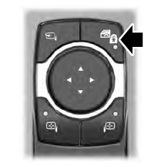
    When the child safety locks are set, you cannot open the rear doors from the inside.
    Lincoln Aviator. Child Safety Locks

    The child safety lock control is on the driver door.

    Press the control to switch the child safety locks on. Press the control again to switch them off. A light on the child safety control illuminates when you switch them on.

    read more

     
    Copyright © 2024 www.liaviator2.com