Lincoln Aviator 2020-2025 Service Manual / Electrical / Battery and Charging System / High Voltage Battery Charging System / Removal and Installation - Charge Status Indicator (CSI) - Plug-In Hybrid Electric Vehicle (PHEV)
Lincoln Aviator: High Voltage Battery Charging System / Removal and Installation - Charge Status Indicator (CSI) - Plug-In Hybrid Electric Vehicle (PHEV)
Removal
-
Refer to: Health and Safety Precautions (100-00 General Information, Description and Operation)..jpg) WARNING:
Before beginning any service procedure in this
section, refer to Safety Warnings in section 100-00 General Information.
Failure to follow this instruction may result in serious personal
injury.
WARNING:
Before beginning any service procedure in this
section, refer to Safety Warnings in section 100-00 General Information.
Failure to follow this instruction may result in serious personal
injury.
-
With the vehicle in NEUTRAL, position it on a hoist.
Refer to: Jacking and Lifting (100-02 Jacking and Lifting, Description and Operation).
-
Disconnect the battery negative terminal.
Refer to: Battery Disconnect and Connect (414-01 Battery, Mounting and Cables, General Procedures).
-
Open the charge status indicator door.
.jpg) |
-
Remove the LH side fender splash shield.
Refer to: Fender Splash Shield (501-02 Front End Body Panels, Removal and Installation).
-
Disconnect the electrical connector.
.jpg) |
-
Release the clips and pull the charge status indicator door housing away from the vehicle.
.jpg) |
-
NOTE: This step is only necessary when installing a new component.
-
Remove the screws.
-
Release the retaining tab back and remove the charge port light ring.
-
Remove the screws.
.jpg) |
Installation
-
To install, reverse the removal procedure.
 Removal and Installation - Secondary On-Board Diagnostic Control Module A (SOBDM) - Plug-In Hybrid Electric Vehicle (PHEV)
Special Tool(s) /
General Equipment
Hose Clamp(s)
Removal
WARNING:
Before beginning any service procedure in this
section, refer to Safety Warnings in section 100-00 General Information...
Other information:
Lincoln Aviator 2020-2025 Service Manual: Description and Operation - Lane Keeping System - System Operation and Component Description
System Operation Lane Keeping Alert and Lane Keeping Aid Item Description 1 Lane Keeping System Switch 2 IPMA 3 GWM 4 Camera Windshield Defrost Heater 5 RCM 6 SCCM 7 PCM 8 IPC 9 TRM 10 BCM 11 PSCM 12 with active cruise control 13 CCM 14 Windshield Network Message Chart Module Network Input Messages - IPMA Broadcast Message Originating Module Message Purpose Ambient air temperature filtered PCM Used to control the camera windshield defrost heater operation...
Lincoln Aviator 2020-2025 Owners Manual: Side Airbags and Driver and Passenger Knee Airbags
Side Airbags WARNING: Do not place objects or mount equipment on or near the airbag cover, on the side of the front or rear seatbacks, or in areas that may come into contact with a deploying airbag. Failure to follow these instructions may increase the risk of personal injury in the event of a crash...
Categories
- Manuals Home
- Lincoln Aviator Owners Manual
- Lincoln Aviator Service Manual
- Configuring The Head Up Display
- Remove and Reinstall the Battery
- Anti-Theft Alarm
- New on site
- Most important about car
Remote Control
Passive Key

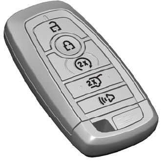
The passive key operates the power locks and the remote start system. The passive key must be in your vehicle to use the push button start.
Note: You may not be able to shift out of park (P) unless the passive key is inside your vehicle.
Copyright © 2025 www.liaviator2.com

