Lincoln Aviator: Supplementary Restraints System / Side Airbags and Driver and Passenger Knee Airbags
Side Airbags
WARNING: Do not place objects or mount equipment on or near the airbag cover, on the side of the front or rear seatbacks, or in areas that may come into contact with a deploying airbag. Failure to follow these instructions may increase the risk of personal injury in the event of a crash.
WARNING: Accessory seat covers not released by Ford Motor Company could prevent the deployment of the airbags and increase the risk of injuries in a crash.
WARNING: Do not lean your head on the door. The side airbag could injure you as it deploys from the side of the seatback.
WARNING: Do not attempt to service, repair, or modify the supplementary restraint system or associated components. Failure to follow this instruction could result in personal injury or death.
WARNING: If a supplementary restraint system component has deployed, it will not function again. Have the system and associated components inspected as soon as possible. Failure to follow this instruction could result in personal injury or death.
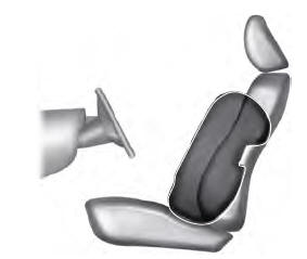
The side airbags are on the outermost side of the front seat backrests. In certain sideways crashes or rollover events, the side airbags will be inflated. The airbag was designed to inflate between the door panel and occupant to further enhance the protection provided to occupants in side impact crashes.
The system consists of the following:
- A label or embossed side panel indicating that your vehicle has side airbags.
- Side airbags inside the driver and front passenger seat backrests.
 Crash sensors and monitoring
system with readiness indicator.
Crash sensors and monitoring
system with readiness indicator.
The design and development of the side airbag system included recommended testing procedures that were developed by a group of automotive safety experts known as the Side Airbag Technical Working Group. These recommended testing procedures help reduce the risk of injuries related to the deployment of side airbags.
Driver and Passenger Knee Airbags
Driver and passenger knee airbags are located under or within the instrument panel. During a crash, the restraints control module may activate the driver and passenger knee airbags (individually or both) based on crash severity and respective occupant conditions. Under certain crash and occupant conditions, the driver and passenger knee airbags may deploy (individually or both) but the corresponding front airbag may not activate. As with front and side airbags, it is important to be properly seated and restrained to reduce the risk of death or serious injury.
 Make sure the knee airbags are
operating properly.
Make sure the knee airbags are
operating properly.
 Front Passenger Sensing System
WARNING: Even with advanced
restraints systems, properly restrain
children 12 and under in a rear seating
position. Failure to follow this could
seriously increase the risk of injury or
death...
 Safety Canopy™
WARNING: Do not place objects or
mount equipment on or near the headliner
at the siderail that may come into contact
with a deploying curtain airbag...
Other information:
Lincoln Aviator 2020-2026 Service Manual: Description and Operation - Rear View Mirrors - System Operation and Component Description
System Operation System Diagram - Exterior, Power, Without Memory Item Description 1 Exterior mirror control switch 2 LH front door window control switch 3 LIN 4 MS-CAN 5 DDM 6 PDM 7 LH exterior mirror 8 RH exterior mirror Network Message Chart Module Network Input Messages — PDM Broadcast Message Originating Module Message Purpose Passenger mirror command DDM Contains the movement requests for the RH exterior mirror glass generated by the exterior mirror control switch...
Lincoln Aviator 2020-2026 Owners Manual: Phone as a Key Backup Starting Passcode
Note: In order to use the Backup Start Passcode feature, Phone as a Key must be active and enabled on at least one phone. If you are unable to start your vehicle, do the following: Fully depress the brake pedal. SYNC displays the Backup Starting Passcode entry screen...
Categories
- Manuals Home
- Lincoln Aviator Owners Manual
- Lincoln Aviator Service Manual
- Anti-Theft Alarm
- Remove and Reinstall the Battery
- USB Port and Power Point Locations
- New on site
- Most important about car
Adjusting the Steering Wheel - Vehicles With: Manual Adjustable Steering Column
WARNING: Do not adjust the steering wheel when your vehicle is moving.
Note: Make sure that you are sitting in the correct position.
Unlock the steering column. Adjust the steering wheel to the desired position.