Lincoln Aviator 2020-2025 Service Manual / Electrical / Battery and Charging System / High Voltage Battery Charging System / Removal and Installation - Charge Port - Plug-In Hybrid Electric Vehicle (PHEV)
Lincoln Aviator: High Voltage Battery Charging System / Removal and Installation - Charge Port - Plug-In Hybrid Electric Vehicle (PHEV)
Removal
NOTE: Removal steps in this procedure may contain installation details.
-
Refer to: Health and Safety Precautions (100-00 General Information, Description and Operation)..jpg) WARNING:
Before beginning any service procedure in this
section, refer to Safety Warnings in section 100-00 General Information.
Failure to follow this instruction may result in serious personal
injury.
WARNING:
Before beginning any service procedure in this
section, refer to Safety Warnings in section 100-00 General Information.
Failure to follow this instruction may result in serious personal
injury.
-
Refer to: Jacking and Lifting (100-02 Jacking and Lifting, Description and Operation).
-
De-energize the high voltage system.
Refer to: High Voltage System De-energizing (414-03A High Voltage Battery, Mounting and Cables, General Procedures).
-
-
Remove the retainer.
-
Remove the push pins and the fender trim panel.
-
Remove the retainer.
.jpg) |
-
Remove the LH headlight assembly.
Refer to: Headlamp Assembly (417-01 Exterior Lighting, Removal and Installation).
-
Disconnect the electrical connector and detach the wire harness retainer.
.jpg) |
-
Detach the wire harness retainers.
.jpg) |
-
Remove the LH side fender splash shield.
Refer to: Fender Splash Shield (501-02 Front End Body Panels, Removal and Installation).
-
-
Remove the bolt.
Torque: 97 lb.in (11 Nm)
-
Disconnect the electrical connector.
-
Slide and detach the wire harness retainer.
-
Detach the wire harness retainer.
-
Remove the bolt.
.jpg) |
-
Remove the CSI.
Refer to: Charge Status Indicator (CSI) - Plug-In Hybrid Electric Vehicle (PHEV) (414-03B High Voltage Battery Charging System, Removal and Installation).
-
Remove the screws and the charge port harness.
Torque: 97 lb.in (11 Nm)
.jpg) |
Installation
-
To install, reverse the removal procedure.
 Diagnosis and Testing - High Voltage Battery Charging System - Plug-In Hybrid Electric Vehicle (PHEV)
Diagnostic Trouble Code (DTC) Chart
Diagnostics in this manual assume a certain skill level and knowledge of Ford-specific diagnostic practices. REFER to: Diagnostic Methods (100-00 General Information, Description and Operation)...
 Removal and Installation - Secondary On-Board Diagnostic Control Module A (SOBDM) - Plug-In Hybrid Electric Vehicle (PHEV)
Special Tool(s) /
General Equipment
Hose Clamp(s)
Removal
WARNING:
Before beginning any service procedure in this
section, refer to Safety Warnings in section 100-00 General Information...
Other information:
Lincoln Aviator 2020-2025 Service Manual: Removal and Installation - Spark Plugs
Removal Remove the ignition coil-on-plugs. Refer to: Ignition Coil-On-Plug (303-07A Engine Ignition - 3.0L EcoBoost, Removal and Installation). Use compressed air to remove any foreign material in the spark plug well before removing the spark plugs...
Lincoln Aviator 2020-2025 Service Manual: Diagnosis and Testing - Instrument Panel and Interior Switches Illumination
Diagnostic Trouble Code (DTC) Chart Diagnostics in this manual assume a certain skill level and knowledge of Ford-specific diagnostic practices. REFER to: Diagnostic Methods (100-00 General Information, Description and Operation). Diagnostic Trouble Code Chart Module DTC Description Action BCM B1314:11 White Lighting (Reflective Controls) Illumination Output: Circuit Short To Ground GO to Pinpoint Test I BCM B1314:15 White Lighting (Reflective Controls) Illumination Output: Circuit Short To Battery or Open GO to Pinpoint Test I BCM B1315:11 Backlighting (Non Reflective Controls) Illumination Output: Circuit Short To Ground GO to Pinpoint Test C BCM B1315:15 Backlighting (Non Reflective Controls) Illumination Output: Circuit Short To Battery or Open GO to Pinpoint Test C DCME B1170:11 Back Light: Circuit Short To Ground GO to Pinpoint Test J DCMF B1170:11 Back Light: Circuit Short To Ground GO to Pinpoint Test J DCMG B1170:11 Back Light: Circuit Short To Ground GO to Pinpoint Test J DCMH B1170:11 Back Light: Circuit Short To Ground GO to Pinpoint Test J DDM B12FF:11 Rear Door Switch Illumination: Circuit Short To Ground GO to Pinpoint Test G DDM B12FF:15 Rear Door Switch Illumination: Circuit Short To Battery or Open GO to Pinpoint Test G DDM U2010:11 Switch Illumination: Circuit Short to Ground GO to Pinpoint Test E DDM U2010:15 Switch Illumination: Circuit Short To Battery or Open GO to Pinpoint Test E PDM B12FF:11 Rear Door Switch Illumination: Circuit Short To Ground GO to Pinpoint Test H PDM B12FF:15 Rear Door Switch Illumination: Circuit Short To Battery or Open GO to Pinpoint Test H PDM U2010:11 Switch Illumination: Circuit Short to Ground GO to Pinpoint Test F PDM U2010:15 Switch Illumination: Circuit Short To Battery or Open GO to Pinpoint Test F Symptom Chart Diagnostics in this manual assume a certain skill level and knowledge of Ford-specific diagnostic practices...
Categories
- Manuals Home
- Lincoln Aviator Owners Manual
- Lincoln Aviator Service Manual
- Opening and Closing the Hood
- Locking and Unlocking
- Interior Lamps
- New on site
- Most important about car
Locking and Unlocking the Doors from Inside

Locking the Doors
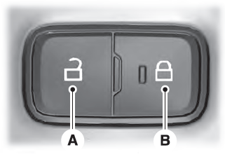
Press the lock switch on the door interior trim panel. The doors can no longer be released using the exterior door handle switches and the luggage compartment locks.
Copyright © 2025 www.liaviator2.com
