Lincoln Aviator: Engine Ignition - 3.0L EcoBoost / Removal and Installation - Spark Plugs
Removal
-
Remove the ignition coil-on-plugs.
Refer to: Ignition Coil-On-Plug (303-07A Engine Ignition - 3.0L EcoBoost, Removal and Installation).
-
Use compressed air to remove any foreign material in the spark plug well before removing the spark plugs.
-
NOTICE: Do not remove the spark plugs when the engine is hot or cold soaked. Spark plug thread or cylinder head damage can occur. Make sure that the engine is warm (hand touch after cooling down) prior to spark plug removal.
NOTICE: If a spark plug is dropped, internal damage may result and the spark plug must be discarded. The use of a damaged spark plug may cause cylinder misfire resulting in engine damage.
Remove the spark plugs.
.jpg) |
-
Inspect the spark plugs.
Refer to: Spark Plug Inspection (303-00 Engine System - General Information, General Procedures).
Installation
-
NOTICE: If a spark plug is dropped, internal damage may result and the spark plug must be discarded. The use of a damaged spark plug may cause cylinder misfire resulting in engine damage.
Install and tighten the spark plugs.
Torque: 133 lb.in (15 Nm)
.jpg) |
-
Install the ignition coil-on-plugs.
Refer to: Ignition Coil-On-Plug (303-07A Engine Ignition - 3.0L EcoBoost, Removal and Installation).
 Diagnosis and Testing - Engine Ignition
Diagnostic Trouble Code (DTC) Chart
Diagnostics in this manual assume a certain skill level and knowledge of Ford-specific diagnostic practices.REFER to: Diagnostic Methods (100-00 General Information, Description and Operation)...
 Removal and Installation - Ignition Coil-On-Plug
Special Tool(s) /
General Equipment
Side Cutter Pliers
Removal
Remove the retainers and the RH side engine compartment cover.
Remove the retainers and the LH side engine compartment cover...
Other information:
Lincoln Aviator 2020-2026 Service Manual: General Procedures - Air Conditioning (A/C) Clutch Air Gap Adjustment - Vehicles With: R134A Refrigerant/R1234YF Refrigerant
Activation NOTE: Compressor with a spring rubber clutch shown others similar. Check the A/C clutch air gap at 3 equally spaced places between the clutch plate and the A/C clutch pulley. Refer to Specifications in Group 412. Remove the A/C clutch...
Lincoln Aviator 2020-2026 Service Manual: Removal and Installation - Axle Housing Bushing
Special Tool(s) / General Equipment 205-1066Installer, Bushing Flat Headed Screw Driver Removal NOTE: Only worn or damaged bushings need to be replaced. Remove the rear axle assembly. Refer to: Axle Assembly (205-02 Rear Drive Axle/Differential, Removal and Installation)...
Categories
- Manuals Home
- Lincoln Aviator Owners Manual
- Lincoln Aviator Service Manual
- Locking and Unlocking
- Wireless Accessory Charger (If Equipped)
- Body and Paint
- New on site
- Most important about car
Activating Intelligent Access
The intelligent access key must be within 3 ft (1 m) of the door or luggage compartment you intend to lock or unlock.
At a Door
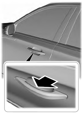
Electronic door handles are on each door. Gently depress the switch inside the exterior door handle to unlock and open the door. An unlock symbol illuminates on the door window trim indicating your vehicle is unlocked.

