Lincoln Aviator: Electric Vehicle Information / Charge Preferences

Touch the button to access Charge Time and Departure Time settings. Additional information and settings are displayed on the charge settings screen once Charge Time or Departure Times are set up.

Lincoln Aviator. Charge Preferences

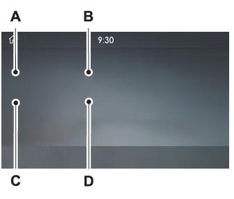
  1. Charge Times on and off switch.
  2. Charge time location name.
  3. Departure Times on and off switch.
  4. Next departure time and cabin temperature.

Charge Times On and Off Switch

This switch is visible when your vehicle is at a saved Charge Times location. Use the switch to turn your charge time settings on and off for this location.

Charge Times Location Name

Displays when your vehicle is at a saved Charge Times location.

Departure Times On and Off Switch

This switch is visible when you have at least one departure time set. Use this switch to turn all departure times on and off. Switching departure times off does not delete your settings.

Next Departure Times and Cabin Temperature

Displays the next departure time and associated cabin temperature setting.

    Charge Settings

    The Charge Settings information for your plug-in hybrid vehicle is available through the Home screen or under Vehicle Settings. To Improve your charging experience, your vehicle has the following convenience features...

    Charge Time Settings

    Follow these steps to set a preferred charge time for a charging location. Select Charge Preferences on the Charge Settings screen. Select Charge Time Setup on the Edit Charge Preferences screen...

    Other information:

    Lincoln Aviator 2020-2025 Service Manual: Diagnosis and Testing - Blind Spot Information System


    Diagnostic Trouble Code (DTC) Chart Diagnostics in this manual assume a certain skill level and knowledge of Ford-specific diagnostic practices. REFER to: Diagnostic Methods (100-00 General Information, Description and Operation).   Diagnostic Trouble Code Chart Module   DTC Description Action   DDM B118C:11 Left Blind Spot Warning Indicator: Circuit Short To Ground   GO to Pinpoint Test D   DDM B118C:15 Left Blind Spot Warning Indicator: Circuit Short To Battery Or Open   GO to Pinpoint Test C   DDM B118C:15 Left Blind Spot Warning Indicator: Circuit Short To Battery Or Open   GO to Pinpoint Test D   PDM B118D:11 Right Blind Spot Warning Indicator: Circuit Short To Ground   GO to Pinpoint Test D   PDM B118D:15 Right Blind Spot Warning Indicator: Circuit Short To Battery Or Open   GO to Pinpoint Test C   PDM B118D:15 Right Blind Spot Warning Indicator: Circuit Short To Battery Or Open   GO to Pinpoint Test D   SODL B11D6:11 Driver Display Alert LED: Circuit Short To Ground   GO to Pinpoint Test V   SODL B11D6:15 Driver Display Alert LED: Circuit Short To Battery Or Open   GO to Pinpoint Test V   SODL U0100:00 Lost Communication With ECM/PCM "A": No Sub Type Information   GO to Pinpoint Test G   SODL U0101:00 Lost Communication with TCM: No Sub Type Information   GO to Pinpoint Test G   SODL U0121:00 Lost Communication With Anti-Lock Brake System (ABS) Control Module "A": No Sub Type Information   GO to Pinpoint Test O   SODL U0140:00 Lost Communication With Body Control Module: No Sub Type Information   GO to Pinpoint Test P   SODL U0146:00 Lost Communication With Serial Data Gateway "A": No Sub Type Information   GO to Pinpoint Test H   SODL U0151:00 Lost Communication With Restraints Control Module: No Sub Type Information   GO to Pinpoint Test Q   SODL U0155:00 Lost Communication With Instrument Panel Cluster (IPC) Control Module: No Sub Type Information   GO to Pinpoint Test R   SODL U0199:00 Lost Communication With "Door Control Module A": No Sub Type Information   GO to Pinpoint Test I   SODL U0232:00 Lost Communication With Side Obstacle Detection Control Module "A": No Sub Type Information   GO to Pinpoint Test S   SODL U0232:87 Lost Communication With Side Obstacle Detection Control Module "A": Missing Message   GO to Pinpoint Test S   SODL U0401:86 Invalid Data Received from ECM/PCM A: Signal Invalid   GO to Pinpoint Test M   SODL U0402:86 Invalid Data Received from TCM: Signal Invalid   GO to Pinpoint Test M   SODL U0415:86 Invalid Data Received from Anti-Lock Brake System (ABS) Control Module "A": Signal Invalid   GO to Pinpoint Test T   SODL U049A:86 Invalid Data Received From "Door Control Module A": Signal Invalid   GO to Pinpoint Test M   SODL U0533:62 Invalid Data Received From Side Obstacle Detection Control Module "A": Signal Compare Failure   GO to Pinpoint Test U   SODL U2100:00 Initial Configuration Not Complete: No Sub Type Information   GO to Pinpoint Test N   SODL U2101:00 Control Module Configuration Incompatible: No Sub Type Information   GO to Pinpoint Test N   SODL U2300:55 Central Configuration: Not Configured   GO to Pinpoint Test N   SODL U3000:44 Control Module: Data Memory Failure   GO to Pinpoint Test K   SODL U3000:45 Control Module: Program Memory Failure   GO to Pinpoint Test K   SODL U3000:46 Control Module: Calibration/Parameter Memory Failure   GO to Pinpoint Test K   SODL U3000:49 Control Module: Internal Electronic Failure   GO to Pinpoint Test K   SODL U3002:62 Vehicle Identification Number: Signal Compare Failure   GO to Pinpoint Test N   SODR B11D6:11 Driver Display Alert LED: Circuit Short To Ground   GO to Pinpoint Test V   SODR B11D6:15 Driver Display Alert LED: Circuit Short To Battery Or Open   GO to Pinpoint Test V   SODR U0100:00 Lost Communication With ECM/PCM "A": No Sub Type Information   GO to Pinpoint Test G   SODR U0101:00 Lost Communication with TCM: No Sub Type Information   GO to Pinpoint Test G   SODR U0121:00 Lost Communication With Anti-Lock Brake System (ABS) Control Module "A": No Sub Type Information   GO to Pinpoint Test O   SODR U0140:00 Lost Communication With Body Control Module: No Sub Type Information   GO to Pinpoint Test P   SODR U0146:00 Lost Communication With Serial Data Gateway "A": No Sub Type Information   GO to Pinpoint Test H   SODR U0151:00 Lost Communication With Restraints Control Module: No Sub Type Information   GO to Pinpoint Test Q   SODR U0155:00 Lost Communication With Instrument Panel Cluster (IPC) Control Module: No Sub Type Information   GO to Pinpoint Test R   SODR U0200:00 Lost Communication With "Door Control Module B": No Sub Type Information   GO to Pinpoint Test J   SODR U0233:00 Lost Communication With Side Obstacle Detection Control Module "B": No Sub Type Information   GO to Pinpoint Test S   SODR U0233:87 Lost Communication With Side Obstacle Detection Control Module "B": Missing Message   GO to Pinpoint Test S   SODR U0401:86 Invalid Data Received from ECM/PCM A: Signal Invalid   GO to Pinpoint Test M   SODR U0402:86 Invalid Data Received from TCM: Signal Invalid   GO to Pinpoint Test M   SODR U0415:86 Invalid Data Received from Anti-Lock Brake System (ABS) Control Module "A": Signal Invalid   GO to Pinpoint Test T   SODR U0501:86 Invalid Data Received From "Door Control Module B": Signal Invalid   GO to Pinpoint Test M   SODR U0534:62 Invalid Data Received From Side Obstacle Detection Control Module "B": Signal Compare Failure   GO to Pinpoint Test U   SODR U2100:00 Initial Configuration Not Complete: No Sub Type Information   GO to Pinpoint Test N   SODR U2101:00 Control Module Configuration Incompatible: No Sub Type Information   GO to Pinpoint Test N   SODR U2300:55 Central Configuration: Not configured   GO to Pinpoint Test N   SODR U3000:44 Control Module: Data Memory Failure   GO to Pinpoint Test K   SODR U3000:45 Control Module: Program Memory Failure   GO to Pinpoint Test K   SODR U3000:46 Control Module: Calibration/Parameter Memory Failure   GO to Pinpoint Test K   SODR U3000:49 Control Module: Internal Electronic Failure   GO to Pinpoint Test K   SODR U3002:62 Vehicle Identification Number: Signal Compare Failure   GO to Pinpoint Test N Global Customer Symptom Code (GCSC) Chart Diagnostics in this manual assume a certain skill level and knowledge of Ford-specific diagnostic practices...

    Lincoln Aviator 2020-2025 Service Manual: Removal and Installation - Liftgate Latch


    Removal NOTE: Removal steps in this procedure may contain installation details. Remove the liftgate trim panel. Refer to: Liftgate Trim Panel (501-05 Interior Trim and Ornamentation, Removal and Installation). Remove the liftgate latch bolts...

    Categories

    Child Safety Locks

    When the child safety locks are set, you cannot open the rear doors from the inside.

    Lincoln Aviator. Child Safety Locks

    The child safety lock control is on the driver door.

    Press the control to switch the child safety locks on. Press the control again to switch them off. A light on the child safety control illuminates when you switch them on.

    read more

     
    Copyright © 2025 www.liaviator2.com