Lincoln Aviator: Automatic Transmission - 10-Speed Automatic Transmission – 10R60 / Description and Operation - E Clutch
Overview
.jpg)
| Item | Description |
| 1 | SSE |
| 2 | E clutch control valve |
| 3 | Clutch gain control valve |
| 4 | E clutch apply circuit |
| 5 | E clutch piston |
| 6 | E clutch assembly |
| 7 | Shell and sun gear No. 4 |
Ring gear No. 3 is mechanically connected to sun gear No. 4 and both are connected to the E clutch. When the E clutch applies, torque from the input shaft is transferred to ring gear No. 3 and sun gear No. 4.
E Clutch Exploded View
.jpg)
| Item | Description |
| 1 | Ring gear No. 3 |
| 2 | E clutch hub |
| 3 | E clutch pressure plate (select fit) |
| 4 | E clutch friction plates (quantity model dependent) |
| 5 | E clutch steel plates (quantity model dependent) |
| 6 | E clutch apply plate (2.9-3.0 mm) |
| 7 | E clutch piston return spring |
| 8 | E clutch piston |
| 9 | E clutch balance dam |
| 10 | Shell and sun gear No. 4 |
E Clutch Hydraulic Circuits
.jpg)
| Item | Description |
| 1 | Line pressure |
| 2 | Pump output |
| 3 | E clutch control valve |
| 4 | SSE |
| 5 | D clutch control valve |
| 6 | SSD |
| 7 | D clutch apply pressure to clutch gain control valve |
| 8 | Clutch gain control valve |
| 9 | LPC solenoid |
| 10 | LPC pressure |
| 11 | E clutch feedback pressure |
| 12 | Apply pressure to mechanical E clutch |
| 13 | Mechanical E clutch |
| 14 | E clutch apply pressure to clutch gain control valve |
| 15 | D clutch feedback pressure |
| 16 | Elevated exhaust pressure |
| 17 | Clutch exhaust |
E Clutch Hydraulic Operation 5th-6th Shift
Line pressure is supplied to the E clutch control valve. LPC pressure is supplied to the gain control valve. LPC pressure positions the gain control valve to the right end of the valve bore. As SSE turns on, it moves the E clutch control valve allowing regulated line pressure to flow to the mechanical E clutch.
E Clutch Hydraulic Operation 2nd-3rd, 4th-5th, and 9th-10th Shifts
Line pressure is supplied to the E clutch control valve. LPC pressure is supplied to the gain control valve. The LPC pressure is low and the gain control valve stays in the default position at the left end of the valve bore. As SSE turns on, it moves the D clutch control valve allowing regulated line pressure to flow to the mechanical E clutch.
E Clutch Hydraulic Passages
.jpg)
.jpg)
.jpg)
 Description and Operation - D Clutch
Overview
Item
Description
1
SSD
2
D clutch control valve
3
Clutch gain control valve
4
D clutch apply circuit
5
D clutch piston
6
D clutch assembly
7
Planetary carrier No...
 Description and Operation - F Clutch
Overview
Item
Description
1
SSF
2
F clutch control valve
3
F clutch latch valve
4
F clutch apply circuit
5
F clutch piston
6
F clutch assembly
7
Ring gear No...
Other information:
Lincoln Aviator 2020-2026 Owners Manual: Opening and Closing the Hood
Opening the Hood Open the left-hand front door. Fully pull the hood release lever and let it completely retract.Note: This action releases the hood latch. Fully pull the hood release lever for a second time.Note: This action fully releases the hood...
Lincoln Aviator 2020-2026 Owners Manual: Creating a Vehicle Wi-Fi Hotspot
You can create a Wi-Fi hotspot in your vehicle and allow devices to connect to it for access to the Internet. Select the settings option on the feature bar. Press Lincoln Connect. Press Vehicle Hotspot.Note: The vehicle hotspot default setting is on...
Categories
- Manuals Home
- Lincoln Aviator Owners Manual
- Lincoln Aviator Service Manual
- Wireless Accessory Charger (If Equipped)
- Disabling Auto-Start-Stop
- Tire Change Procedure
- New on site
- Most important about car
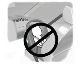
Children and Airbags
WARNING: Airbags can kill or injure a child in a child restraint. Never place a rear-facing child restraint in front of an active airbag. If you must use a forward-facing child restraint in the front seat, move the seat upon which the child restraint is installed all the way back.

