Lincoln Aviator 2020-2026 Service Manual / Body and Paint / Frame and Mounting / Uni-Body, Subframe and Mounting System / Description and Operation - Frame Assembly - Overview
Lincoln Aviator: Uni-Body, Subframe and Mounting System / Description and Operation - Frame Assembly - Overview
Overview
The front subframe is bolted to the body and is used to:
- aid in structural support.
- provide mounting surfaces for the steering gear.
- provide mounting surfaces for the front suspension lower control arms, the engine mounts and for the front stabilizer bar.
The rear subframe is bolted to the body and is used to:
- aid in structural support.
- provide mounting surfaces for the rear suspension lower arms and upper arms.
The transmission support crossmember is bolted to the body and is used to:
- provide support to transfer case and transmission.
For body dimension specifications,
Refer to: Body and Frame (501-26 Body Repairs - Vehicle Specific Information and Tolerance Checks, Description and Operation).
 Removal and Installation - Front Subframe
Special Tool(s) /
General Equipment
303-050
(T70P-6000)
Lifting Bracket, Engine
303-F070Support Bar, EngineTKIT-1999A-F/LTTKIT-1999A-FM/FLM
Removal
NOTICE:
Suspension fasteners are critical parts that affect
performance of vital components and systems...
Other information:
Lincoln Aviator 2020-2026 Owners Manual: Phone as a Key Backup Starting Passcode
Note: In order to use the Backup Start Passcode feature, Phone as a Key must be active and enabled on at least one phone. If you are unable to start your vehicle, do the following: Fully depress the brake pedal. SYNC displays the Backup Starting Passcode entry screen...
Lincoln Aviator 2020-2026 Service Manual: Removal and Installation - Driver Side Register
Removal Release the clips and remove the LH instrument panel end cap. Release the clips and remove the RH instrument panel trim panel. Remove the screws, release the clips and remove the driver side register assembly...
Categories
- Manuals Home
- Lincoln Aviator Owners Manual
- Lincoln Aviator Service Manual
- Anti-Theft Alarm
- Tire Change Procedure
- Changing the Front Wiper Blades - Vehicles With: Heated Wiper Blades
- New on site
- Most important about car
Activating Intelligent Access
The intelligent access key must be within 3 ft (1 m) of the door or luggage compartment you intend to lock or unlock.
At a Door
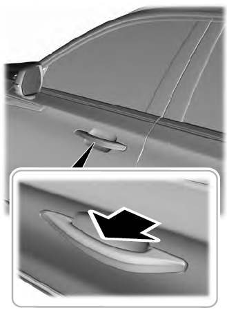
Electronic door handles are on each door. Gently depress the switch inside the exterior door handle to unlock and open the door. An unlock symbol illuminates on the door window trim indicating your vehicle is unlocked.

Copyright © 2026 www.liaviator2.com

