Lincoln Aviator 2020-2025 Service Manual / Chassis / Driveline / Front Drive Axle/Differential / Description and Operation - Front Drive Axle and Differential

Lincoln Aviator: Front Drive Axle/Differential / Description and Operation - Front Drive Axle and Differential

The 6.5-inch ring gear rear differential axle has 3.31, 3.58 and 3.73 gear ratio versions.

Front Drive Axle and Differential

The front drive axle consists of:

  • A cast-aluminum center section, a removable cast-aluminum differential housing cover
  • Integral-type housing hypoid gear design (center of the pinion set below the centerline of the ring gear). Two opposed tapered roller bearings support the drive pinion in the axle housing
  • A drive pinion collapsible spacer, located on the pinion shaft, maintains pinion bearing preload. The pinion nut adjusts the preload
  • Differential bearing shims, located between the differential bearing cups and the axle housing, adjust the differential bearing preload and the ring gear backlash
  • A differential case, a 1-piece design with 2 openings to allow for assembly of the internal components and lubricant flow. Two opposed tapered roller bearings (differential bearings) support the differential case in the axle housing. Removable differential bearing caps retain the differential assembly in the axle housing
  • The bar code tag located on the RH side differential assembly contains the axle information

The front drive axle receives input from the transfer case by way of the front driveshaft. Rotational torque is transferred through the drive pinion to the ring gear, which in turn drives the differential case. Inside the differential case are the pinion gears which rotate on the stationary pinion shaft and the side gears which are splined to the axle shafts. The differential assembly is a gear arrangement that allows the drive wheels to be driven at different speeds and divides the input torque of the pinion gear between the axle halfshafts. The front axle transmits torque only and carries no vehicle load. CV-joints located at each end of the halfshafts allow the axle to remain stationary in relationship to front wheels, yet articulate at the knuckle. These CV-joints permit the wheels to be driven and turned at the same time.

    Specifications

      Materials Name Specification Motorcraft® SAE 75W-140 Synthetic Rear Axle Lubricant / XY-75W140-QL WSL-M2C192-A Motorcraft® High Temperature 4x4 Front Axle and Wheel Bearing Grease XG-11 WSS-M1C267-A1   Capacities Item Liters   Material: Motorcraft® SAE 75W-140 Synthetic Rear Axle Lubricant / XY-75W140-QL (WSL-M2C192-A) 0...

    Diagnosis and Testing - Front Drive Axle

    Principles of Operation Inspection and Verification Verify the customer concern. Visually inspect for obvious signs of mechanical or electrical damage...

    Other information:

    Lincoln Aviator 2020-2025 Service Manual: Diagnosis and Testing - Body System


    Symptom Chart(s) Diagnostics in this manual assume a certain skill level and knowledge of Ford-specific diagnostic practices. REFER to: Diagnostic Methods (100-00 General Information, Description and Operation). Dust and Water Leaks Most dust and water leaks occur due to missing or incorrectly installed body sealer or components...

    Lincoln Aviator 2020-2025 Service Manual: Diagnosis and Testing - Blind Spot Information System


    Diagnostic Trouble Code (DTC) Chart Diagnostics in this manual assume a certain skill level and knowledge of Ford-specific diagnostic practices. REFER to: Diagnostic Methods (100-00 General Information, Description and Operation).   Diagnostic Trouble Code Chart Module   DTC Description Action   DDM B118C:11 Left Blind Spot Warning Indicator: Circuit Short To Ground   GO to Pinpoint Test D   DDM B118C:15 Left Blind Spot Warning Indicator: Circuit Short To Battery Or Open   GO to Pinpoint Test C   DDM B118C:15 Left Blind Spot Warning Indicator: Circuit Short To Battery Or Open   GO to Pinpoint Test D   PDM B118D:11 Right Blind Spot Warning Indicator: Circuit Short To Ground   GO to Pinpoint Test D   PDM B118D:15 Right Blind Spot Warning Indicator: Circuit Short To Battery Or Open   GO to Pinpoint Test C   PDM B118D:15 Right Blind Spot Warning Indicator: Circuit Short To Battery Or Open   GO to Pinpoint Test D   SODL B11D6:11 Driver Display Alert LED: Circuit Short To Ground   GO to Pinpoint Test V   SODL B11D6:15 Driver Display Alert LED: Circuit Short To Battery Or Open   GO to Pinpoint Test V   SODL U0100:00 Lost Communication With ECM/PCM "A": No Sub Type Information   GO to Pinpoint Test G   SODL U0101:00 Lost Communication with TCM: No Sub Type Information   GO to Pinpoint Test G   SODL U0121:00 Lost Communication With Anti-Lock Brake System (ABS) Control Module "A": No Sub Type Information   GO to Pinpoint Test O   SODL U0140:00 Lost Communication With Body Control Module: No Sub Type Information   GO to Pinpoint Test P   SODL U0146:00 Lost Communication With Serial Data Gateway "A": No Sub Type Information   GO to Pinpoint Test H   SODL U0151:00 Lost Communication With Restraints Control Module: No Sub Type Information   GO to Pinpoint Test Q   SODL U0155:00 Lost Communication With Instrument Panel Cluster (IPC) Control Module: No Sub Type Information   GO to Pinpoint Test R   SODL U0199:00 Lost Communication With "Door Control Module A": No Sub Type Information   GO to Pinpoint Test I   SODL U0232:00 Lost Communication With Side Obstacle Detection Control Module "A": No Sub Type Information   GO to Pinpoint Test S   SODL U0232:87 Lost Communication With Side Obstacle Detection Control Module "A": Missing Message   GO to Pinpoint Test S   SODL U0401:86 Invalid Data Received from ECM/PCM A: Signal Invalid   GO to Pinpoint Test M   SODL U0402:86 Invalid Data Received from TCM: Signal Invalid   GO to Pinpoint Test M   SODL U0415:86 Invalid Data Received from Anti-Lock Brake System (ABS) Control Module "A": Signal Invalid   GO to Pinpoint Test T   SODL U049A:86 Invalid Data Received From "Door Control Module A": Signal Invalid   GO to Pinpoint Test M   SODL U0533:62 Invalid Data Received From Side Obstacle Detection Control Module "A": Signal Compare Failure   GO to Pinpoint Test U   SODL U2100:00 Initial Configuration Not Complete: No Sub Type Information   GO to Pinpoint Test N   SODL U2101:00 Control Module Configuration Incompatible: No Sub Type Information   GO to Pinpoint Test N   SODL U2300:55 Central Configuration: Not Configured   GO to Pinpoint Test N   SODL U3000:44 Control Module: Data Memory Failure   GO to Pinpoint Test K   SODL U3000:45 Control Module: Program Memory Failure   GO to Pinpoint Test K   SODL U3000:46 Control Module: Calibration/Parameter Memory Failure   GO to Pinpoint Test K   SODL U3000:49 Control Module: Internal Electronic Failure   GO to Pinpoint Test K   SODL U3002:62 Vehicle Identification Number: Signal Compare Failure   GO to Pinpoint Test N   SODR B11D6:11 Driver Display Alert LED: Circuit Short To Ground   GO to Pinpoint Test V   SODR B11D6:15 Driver Display Alert LED: Circuit Short To Battery Or Open   GO to Pinpoint Test V   SODR U0100:00 Lost Communication With ECM/PCM "A": No Sub Type Information   GO to Pinpoint Test G   SODR U0101:00 Lost Communication with TCM: No Sub Type Information   GO to Pinpoint Test G   SODR U0121:00 Lost Communication With Anti-Lock Brake System (ABS) Control Module "A": No Sub Type Information   GO to Pinpoint Test O   SODR U0140:00 Lost Communication With Body Control Module: No Sub Type Information   GO to Pinpoint Test P   SODR U0146:00 Lost Communication With Serial Data Gateway "A": No Sub Type Information   GO to Pinpoint Test H   SODR U0151:00 Lost Communication With Restraints Control Module: No Sub Type Information   GO to Pinpoint Test Q   SODR U0155:00 Lost Communication With Instrument Panel Cluster (IPC) Control Module: No Sub Type Information   GO to Pinpoint Test R   SODR U0200:00 Lost Communication With "Door Control Module B": No Sub Type Information   GO to Pinpoint Test J   SODR U0233:00 Lost Communication With Side Obstacle Detection Control Module "B": No Sub Type Information   GO to Pinpoint Test S   SODR U0233:87 Lost Communication With Side Obstacle Detection Control Module "B": Missing Message   GO to Pinpoint Test S   SODR U0401:86 Invalid Data Received from ECM/PCM A: Signal Invalid   GO to Pinpoint Test M   SODR U0402:86 Invalid Data Received from TCM: Signal Invalid   GO to Pinpoint Test M   SODR U0415:86 Invalid Data Received from Anti-Lock Brake System (ABS) Control Module "A": Signal Invalid   GO to Pinpoint Test T   SODR U0501:86 Invalid Data Received From "Door Control Module B": Signal Invalid   GO to Pinpoint Test M   SODR U0534:62 Invalid Data Received From Side Obstacle Detection Control Module "B": Signal Compare Failure   GO to Pinpoint Test U   SODR U2100:00 Initial Configuration Not Complete: No Sub Type Information   GO to Pinpoint Test N   SODR U2101:00 Control Module Configuration Incompatible: No Sub Type Information   GO to Pinpoint Test N   SODR U2300:55 Central Configuration: Not configured   GO to Pinpoint Test N   SODR U3000:44 Control Module: Data Memory Failure   GO to Pinpoint Test K   SODR U3000:45 Control Module: Program Memory Failure   GO to Pinpoint Test K   SODR U3000:46 Control Module: Calibration/Parameter Memory Failure   GO to Pinpoint Test K   SODR U3000:49 Control Module: Internal Electronic Failure   GO to Pinpoint Test K   SODR U3002:62 Vehicle Identification Number: Signal Compare Failure   GO to Pinpoint Test N Global Customer Symptom Code (GCSC) Chart Diagnostics in this manual assume a certain skill level and knowledge of Ford-specific diagnostic practices...

    Categories

    Locking and Unlocking the Doors from Inside
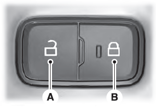
    Lincoln Aviator. Locking and Unlocking the Doors from Inside

    Unlock. Lock.

    Locking the Doors

    Press the lock switch on the door interior trim panel. The doors can no longer be released using the exterior door handle switches and the luggage compartment locks.

    read more

     
    Copyright © 2025 www.liaviator2.com