Lincoln Aviator 2020-2025 Service Manual / Electrical / Battery and Charging System / High Voltage Battery Charging System / Description and Operation - High Voltage Battery Charging System - Plug-In Hybrid Electric Vehicle (PHEV) - Component Location
Lincoln Aviator: High Voltage Battery Charging System / Description and Operation - High Voltage Battery Charging System - Plug-In Hybrid Electric Vehicle (PHEV) - Component Location
.jpg)
| Item | Description |
|---|---|
| 1 | Secondary On-Board Diagnostic Control Module A (SOBDM) |
| 2 | Charge Status Indicator (CSI) |
.jpg)
| Item | Description |
|---|---|
| 1 | Charge port and wiring harness |
 Description and Operation - High Voltage Battery Charging System - Plug-In Hybrid Electric Vehicle (PHEV) - Overview
Overview
The
high voltage battery charging system is responsible for charging the
high voltage battery while the vehicle is not operating. It consists of
an Electric Vehicle Supply Equipment (EVSE), SOBDM and Charge Status Indicator (CSI)...
Other information:
Lincoln Aviator 2020-2025 Service Manual: Removal and Installation - Spring
Removal NOTICE: Suspension fasteners are critical parts that affect the performance of vital components and systems. Failure of these fasteners may result in major service expense. Use the same or equivalent parts if replacement is necessary. Do not use a replacement part of lesser quality or substitute design...
Lincoln Aviator 2020-2025 Service Manual: Description and Operation - B Clutch
Overview Item Description 1 SSB 2 B clutch control valve 3 B clutch latch valve 4 B clutch apply circuit 5 B clutch piston 6 B clutch assembly 7 One-Way Clutch (OWC) 8 Sun gear No...
Categories
- Manuals Home
- Lincoln Aviator Owners Manual
- Lincoln Aviator Service Manual
- Configuring The Head Up Display
- Body and Paint
- Changing the Front Wiper Blades - Vehicles With: Heated Wiper Blades
- New on site
- Most important about car
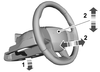
Adjusting the Steering Wheel - Vehicles With: Manual Adjustable Steering Column
WARNING: Do not adjust the steering wheel when your vehicle is moving.
Note: Make sure that you are sitting in the correct position.
Unlock the steering column. Adjust the steering wheel to the desired position.
Copyright © 2025 www.liaviator2.com

