Lincoln Aviator: Rear Suspension / Removal and Installation - Spring
Removal
NOTICE: Suspension fasteners are critical parts that affect the performance of vital components and systems. Failure of these fasteners may result in major service expense. Use the same or equivalent parts if replacement is necessary. Do not use a replacement part of lesser quality or substitute design. Tighten fasteners as specified.
-
Remove the lower arm.
Refer to: Lower Arm (204-02 Rear Suspension, Removal and Installation).
-
Remove the spring.
.jpg) |
Installation
-
Visual check.
Check the upper spring seat for damage. Replace as necessary.
.jpg) |
-
Install the spring.
.jpg) |
-
NOTE: Make sure that the spring is correctly located in the upper spring seat.
Visual check.
Align the spring in the upper spring seat.
.jpg) |
-
Install the lower arm.
Refer to: Lower Arm (204-02 Rear Suspension, Removal and Installation).
 Removal and Installation - Rear Stabilizer Bar Link
Removal
NOTICE:
Suspension fasteners are critical parts that affect the
performance of vital components and systems. Failure of these fasteners
may result in major service expense...
 Removal and Installation - Toe Link
Special Tool(s) /
General Equipment
Vehicle/Axle Stands
Removal
NOTICE:
Suspension fasteners are critical parts that affect the
performance of vital components and systems...
Other information:
Lincoln Aviator 2020-2026 Service Manual: Removal and Installation - SYNC Module [APIM] to Universal Serial Bus (USB) Port Cable
Special Tool(s) / General Equipment Interior Trim Remover Removal NOTE: Removal steps in this procedure may contain installation details. Instrument panel universal serial bus (USB) cable Remove the floor console. Refer to: Floor Console (501-12 Instrument Panel and Console, Removal and Installation)...
Lincoln Aviator 2020-2026 Owners Manual: Automatic Transmission
WARNING: Always fully apply the parking brake and make sure you shift into park (P). Failure to follow this instruction could result in personal injury or death. WARNING: Do not apply the brake pedal and accelerator pedal simultaneously. Applying both pedals simultaneously for more than a few seconds will limit engine performance, which may result in difficulty maintaining speed in traffic and could lead to serious injury...
Categories
- Manuals Home
- Lincoln Aviator Owners Manual
- Lincoln Aviator Service Manual
- Description and Operation - Jacking and Lifting
- Keyless Entry
- Remove and Reinstall the Battery
- New on site
- Most important about car
Activating Intelligent Access
The intelligent access key must be within 3 ft (1 m) of the door or luggage compartment you intend to lock or unlock.
At a Door
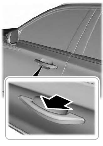
Electronic door handles are on each door. Gently depress the switch inside the exterior door handle to unlock and open the door. An unlock symbol illuminates on the door window trim indicating your vehicle is unlocked.