Lincoln Aviator: Rear Suspension / Removal and Installation - Toe Link
Special Tool(s) / General Equipment
| Vehicle/Axle Stands |
Removal
NOTICE: Suspension fasteners are critical parts that affect the performance of vital components and systems. Failure of these fasteners may result in major service expense. Use the same or equivalent parts if replacement is necessary. Do not use a replacement part of lesser quality or substitute design. Tighten fasteners as specified.
-
Remove the wheel and tire.
Refer to: Wheel and Tire (204-04A Wheels and Tires, Removal and Installation).
-
NOTICE: Do not attempt to jacking on the front control arm or rear control arm on any vehicle. Damage to control arms may occur.
NOTICE: Make sure that the insulator pads are correctly positioned to prevent direct contact with other components.
Raise the suspension to curb height.
Use the General Equipment: Vehicle/Axle Stands
.jpg) |
-
-
NOTE: Index mark the cam adjusters for reference during installation.
Remove and discard the toe link inboard cam bolt and nut.
-
Remove and discard the toe link outboard bolt and remove the toe link.
-
.jpg) |
Installation
-
NOTICE: Tighten the suspension fasteners with the weight of the vehicle on the wheels and tires or use a suitable jack to raise the suspension to curb height or damage to the bushings may occur.
NOTE: Only tighten the nuts and bolts when the suspension is in the normal drive position.
NOTE: Align reference marks made during removal.
-
Install the toe link and install the new outboard toe link bolt.
Torque: 129 lb.ft (175 Nm)
-
Install the new toe link inboard cam bolt and nut.
Torque: 184 lb.ft (250 Nm)
-
Install the toe link and install the new outboard toe link bolt.
.jpg) |
-
Install the wheel and tire.
Refer to: Wheel and Tire (204-04A Wheels and Tires, Removal and Installation).
-
Check and if necessary adjust rear toe.
Refer to: Rear Toe Adjustment (204-00 Suspension System - General Information, General Procedures).
 Removal and Installation - Spring
Removal
NOTICE:
Suspension fasteners are critical parts that affect the
performance of vital components and systems. Failure of these fasteners
may result in major service expense...
 Removal and Installation - Upper Arm
Special Tool(s) /
General Equipment
Vehicle/Axle Stands
Removal
NOTICE:
Suspension fasteners are critical parts that affect the
performance of vital components and systems...
Other information:
Lincoln Aviator 2020-2026 Service Manual: Description and Operation - F Clutch
Overview Item Description 1 SSF 2 F clutch control valve 3 F clutch latch valve 4 F clutch apply circuit 5 F clutch piston 6 F clutch assembly 7 Ring gear No...
Lincoln Aviator 2020-2026 Service Manual: Description and Operation - Universal Transmitter - System Operation and Component Description
System Operation Universal Transmitter The universal transmitter learns a hand-held transmitter radio frequency code and stores the code in memory. It consists of 3 buttons with an indicator lamp. Once the universal transmitter code is stored, the universal transmitter emits the radio frequency of the hand-held transmitter when the corresponding button is pressed...
Categories
- Manuals Home
- Lincoln Aviator Owners Manual
- Lincoln Aviator Service Manual
- Anti-Theft Alarm
- Resetting the System
- Interior Lamps
- New on site
- Most important about car
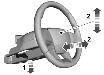
Adjusting the Steering Wheel - Vehicles With: Manual Adjustable Steering Column
WARNING: Do not adjust the steering wheel when your vehicle is moving.
Note: Make sure that you are sitting in the correct position.
Unlock the steering column. Adjust the steering wheel to the desired position.
