Lincoln Aviator 2020-2025 Service Manual / Electrical / Battery and Charging System / High Voltage Battery, Mounting and Cables / Description and Operation - High Voltage Battery, Mounting and Cables - Plug-In Hybrid Electric Vehicle (PHEV) - Component Location
Lincoln Aviator: High Voltage Battery, Mounting and Cables / Description and Operation - High Voltage Battery, Mounting and Cables - Plug-In Hybrid Electric Vehicle (PHEV) - Component Location
.jpg)
| Item | Description |
|---|---|
| 1 | High voltage battery |
.jpg)
| Item | Description |
|---|---|
| 1 | BECM |
| 2 | High voltage battery junction box |
| 3 | Traction battery sensor wiring assembly |
.jpg)
| Item | Description |
|---|---|
| 1 | DC/DC low current fuse |
| 2 | High voltage high current Fuse |
| 3 | AC/PTC low current fuse |
.jpg)
| Item | Description |
|---|---|
| 1 | High Voltage 3 Phase AC -ISC (Inverter system controller) to Hybrid Drive Unit cable |
| 2 | High voltage cable |
| 3 | A/C (air conditioning) compressor high voltage cable |
 Description and Operation - High Voltage Battery, Mounting and Cables - Plug-In Hybrid Electric Vehicle (PHEV) - System Operation and Component Description
System Diagram
Item
Description
1
Current Sensor
2
Contactor Sense Leads
3
BECM
4
Precharge Contactor Coil
5
Positive Contactor Coil
6
Negative Contactor Coil
7
High Voltage Battery Junction Box
8
Temperature Sensors
9
Cell Voltage Sense Leads
10
PCM
11
Battery Cell Arrays
12
GWM
13
RCM
14
DCDC
15
12 Volt Battery Monitoring Sensor
16
TCU (if equipped)
17
Ignition Switch
18
Main 12 Volt Battery
19
HVAC
20
Service Disconnect
21
High Voltage Battery Coolant Diverter Valve
22
Motor Electronics Coolant Pump
23
Isolation Switch (BIB)
24
Auxiliary 12 Volt Battery
25
Coolant Temperature Sensor
26
High Voltage Battery
27
BCM
28
High Voltage Battery Coolant Pump
29
BCMC
30
SOBDMC
31
High Voltage Interlock Loop (HVIL)
32
Auxillary Contactor Coil
33
SOBDM also known as the Battery Charger Control Module (BCCM)
System Operation
Network Message Chart - Battery Energy Control Module (BECM)
Broadcast Message
Originating Module
Message Purpose
12 volt battery voltage
BCM
Battery voltage measured with battery sensor...
 Diagnosis and Testing - High Voltage Battery, Mounting and Cables - Plug-In Hybrid Electric Vehicle (PHEV)
Diagnostic Trouble Code (DTC) Chart
Diagnostics in this manual assume a certain skill level and knowledge of Ford-specific diagnostic practices. REFER to: Diagnostic Methods (100-00 General Information, Description and Operation)...
Other information:
Lincoln Aviator 2020-2025 Service Manual: Description and Operation - Sealer, Underbody Protection Material and Adhesives
Adhesives The correct adhesive bonding is essential to repairing the vehicle correctly. Adhesives and mechanical fasteners are used in certain areas of the body structure in place of welding. In addition to providing a structural bond between components, adhesives can also help prevent wind noise, water leaks, exhaust fumes and dust from entering the vehicle...
Lincoln Aviator 2020-2025 Service Manual: Description and Operation - Low One-Way Clutch Assembly
One-Way Clutch (OWC) Exploded View Item Description 1 Front support assembly 2 One-Way Clutch (OWC) 3 Sun gear No. 1 4 Sun gear No. 2 One-Way Clutch (OWC) Mechanical Operation The One-Way Clutch (OWC) is a brake clutch that holds the sun gears No...
Categories
- Manuals Home
- Lincoln Aviator Owners Manual
- Lincoln Aviator Service Manual
- Keyless Entry
- Child Safety Locks
- Resetting the System
- New on site
- Most important about car
Activating Intelligent Access
The intelligent access key must be within 3 ft (1 m) of the door or luggage compartment you intend to lock or unlock.
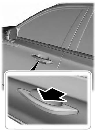
At a Door
Electronic door handles are on each door. Gently depress the switch inside the exterior door handle to unlock and open the door. An unlock symbol illuminates on the door window trim indicating your vehicle is unlocked.

Copyright © 2025 www.liaviator2.com
