Lincoln Aviator: Horn / Description and Operation - Horn - System Operation and Component Description
System Operation
System Diagram- Vehicles Without Adaptive Steering
.jpg)
| Item | Description |
|---|---|
| 1 | Clockspring |
| 2 | Horn switch |
| 3 | SCCM |
| 4 | BCM |
| 5 | BCMC |
| 6 | Horn |
Horn Operation - Vehicles Without Adaptive Steering
The horn switch consists of 2 sets of contacts separated by springs. The lower set is connected to ground and the upper set is connected to the horn signal circuit. When the driver airbag module is pressed, it pushes down on the upper set of contacts, collapsing the springs and allowing the contacts to touch. When the contacts touch, it completes the circuit and provides the ground signal which is routed through the clockspring, SCCM and then to the BCM. The BCM then energizes the non-servicable horn relay located in the BCMC. When energized, the horn relay provides voltage to the horn, enabling the horn to sound.
System Diagram- Vehicles With Adaptive Steering
.jpg)
| Item | Description |
|---|---|
| 1 | BCM |
| 2 | Horn switch |
| 3 | Horn |
| 4 | BCMC |
| 5 | Clockspring |
Horn Operation - Vehicles With Adaptive Steering
The horn switch uses 2 sets of contacts separated by springs. The lower set is connected to ground and the upper set is connected to the horn signal circuit. When the driver airbag is pressed, it pushes down on the upper set of contacts, collapsing the springs and allowing the contacts to touch. When the contacts touch, it completes the circuit and provides a ground signal through the clockspring to the BCM horn input. The BCM then energizes the non-servicable horn relay located in the BCMC. When energized, the horn relay provides voltage to the horn, enabling the horn to sound.
 Diagnosis and Testing - Horn
Diagnostic Trouble Code (DTC) Chart
Diagnostics in this manual assume a certain skill level and knowledge of Ford-specific diagnostic practices. REFER to: Diagnostic Methods (100-00 General Information, Description and Operation)...
Other information:
Lincoln Aviator 2020-2026 Owners Manual: About This Manual
Thank you for choosing Lincoln. We recommend that you take some time to get to know your vehicle by reading this manual. The more that you know about it, the greater the safety and pleasure you will get from driving it. WARNING: Driving while distracted can result in loss of vehicle control, crash and injury...
Lincoln Aviator 2020-2026 Owners Manual: CAUTION: TO REDUCE THE RISK OF FIRE
Use a three-prong AC outlet that is properly grounded, 15-20 amps or greater, and in good condition. Use a dedicated line. You cannot have other appliances connected to the same circuit. If you do not use a dedicated circuit, the circuit breaker could trip or open...
Categories
- Manuals Home
- Lincoln Aviator Owners Manual
- Lincoln Aviator Service Manual
- Anti-Theft Alarm
- Child Safety Locks
- Disabling Auto-Start-Stop
- New on site
- Most important about car
Activating Intelligent Access
The intelligent access key must be within 3 ft (1 m) of the door or luggage compartment you intend to lock or unlock.
At a Door
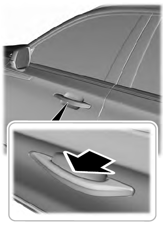
Electronic door handles are on each door. Gently depress the switch inside the exterior door handle to unlock and open the door. An unlock symbol illuminates on the door window trim indicating your vehicle is unlocked.


.jpg)
.jpg)
