Lincoln Aviator: Parking Aid - Vehicles With: Parking Aid Camera / Description and Operation - Parking Aid - Overview
Overview
Rear Only Parking Aid Camera
The rear parking aid camera system visually aids the driver while reversing or reverse parking the vehicle. The camera system has features that provide fixed and active guideline overlays on the video image to assist the driver in aligning the vehicle and a visual alert function that provides a visual highlight in the zone where an object is detected by the audible parking aid system.
360 Degree View Camera
The 360 degree view camera system provides several different camera views to visually aid the driver while maneuvering the vehicle at low speed. The camera system is enabled by selecting reverse gear or pressing the camera selection switch when any gear except reverse is selected. The camera views are changed using the audio system display on-screen camera selection buttons. Available camera views depend on the transmission gear selection. The camera system provides fixed and active guideline overlays on the rear normal view video image to assist the driver in aligning the vehicle and a visual alert function that provides a visual highlight on the rear normal and 360 degree view images in the zone where an object is detected by the audible parking aid system.
 Description and Operation - Parking Aid - System Operation and Component Description
System Operation
Rear Only Parking Aid Camera
System Diagram
Item
Description
1
TRM
2
Rear camera on demand switch
3
Camera video signal (coaxial cable)
4
PCM
5
PAM
6
ABS module
7
PSCM
8
GWM
9
APIM
10
Rear parking aid camera
11
BCM
12
HVAC module
13
Audio system display
Network Message Chart
APIM Network Input Messages
Broadcast Message
Originating Module
Message Purpose
Gear lever position
PCM
Enables the video display when reverse is selected...
Other information:
Lincoln Aviator 2020-2026 Owners Manual: Guarding Against Exhaust Fumes. Important Ventilating Information
Guarding Against Exhaust Fumes WARNING: Exhaust leaks may result in entry of harmful and potentially lethal fumes into the passenger compartment. If you smell exhaust fumes inside your vehicle, have your vehicle inspected immediately. Do not drive if you smell exhaust fumes...
Lincoln Aviator 2020-2026 Service Manual: Removal and Installation - Second Row Blower Motor Control Module
Removal NOTE: Removal steps in this procedure may contain installation details. Remove the floor console. Refer to: Floor Console (501-12 Instrument Panel and Console, Removal and Installation). Remove the bolts the front duct section...
Categories
- Manuals Home
- Lincoln Aviator Owners Manual
- Lincoln Aviator Service Manual
- Wireless Accessory Charger (If Equipped)
- Resetting the System
- Changing the Front Wiper Blades - Vehicles With: Heated Wiper Blades
- New on site
- Most important about car
Child Safety Locks
When the child safety locks are set, you cannot open the rear doors from the inside.

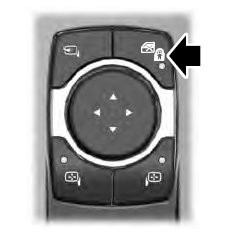
The child safety lock control is on the driver door.
Press the control to switch the child safety locks on. Press the control again to switch them off. A light on the child safety control illuminates when you switch them on.

