Lincoln Aviator: Perimeter Anti-Theft Alarm / Description and Operation - Perimeter Anti-Theft Alarm - Overview
Overview
The perimeter anti-theft alarm system has three operation modes:
- ARMED - The perimeter anti-theft alarm is armed when the ignition is OFF and all vehicle entry points have been electrically locked for 20 seconds.
- ACTIVE - When the perimeter anti-theft alarm activates, the horn sounds and all turn signals and interior courtesy lamps flash. The horn stops sounding after 30 seconds and the lights continue to flash for up to 5 minutes.
- DISARMED - The perimeter anti-theft alarm is disarmed when a vehicle entry point is open or unlocked, or if the ignition is ON.
The panic alarm operates similar to the perimeter alarm, but only activates when the ignition is OFF and the RKE transmitter panic button is used. For additional information of the panic alarm function,
Refer to: Handles, Locks, Latches and Entry Systems - System Operation and Component Description (501-14 Handles, Locks, Latches and Entry Systems, Description and Operation).
Visual
and audible feedback is also provided when locking or unlocking the
vehicle. For detailed information of the vehicle locking and unlocking
feedback,
Refer to: Handles, Locks, Latches and Entry Systems - System Operation and Component Description (501-14 Handles, Locks, Latches and Entry Systems, Description and Operation).
A
switch inhibit feature temporarily disables the door lock control
switches 20 seconds after the vehicle is electronically locked. For
detailed information of the switch inhibit feature,
Refer to: Handles, Locks, Latches and Entry Systems - System Operation and Component Description (501-14 Handles, Locks, Latches and Entry Systems, Description and Operation).
 Description and Operation - Perimeter Anti-Theft Alarm - System Operation and Component Description
System Operation
System Diagram
Item
Description
1
BCM
2
Turn Signals
3
Hood Ajar Switch
4
Liftgate Ajar Switch
5
IPC
6
Courtesy Lamps
7
Passive Key
8
RTM
9
RGTM
10
GWM
11
GWM
12
Intrusion Sensor
13
Horn
14
DLC
15
DCME (Left Front Door)
16
Door Ajar Switch
17
Power Liftgate
18
Manual Liftgate
19
DCMF (Right Front Door)
20
Door Ajar Switch
21
DCMG (Left Rear Door)
22
Door Ajar Switch
23
DCMH (Right Rear Door)
24
Door Ajar Switch
25
DDM
26
PDM
Network Message Chart
BCM Network Input Messages
Broadcast Message
Originating Module
Message Purpose
RKE data
RTM
Used by the BCM to arm/disarm the perimeter alarm or to activate/deactivate the panic alarm...
Other information:
Lincoln Aviator 2020-2026 Service Manual: Removal and Installation - Second Row Seat Backrest Blower Motor
Removal Remove the second row single seat backrest cover. Refer to: Second Row Single Seat Backrest Cover - Vehicles With: Second Row Captain Chairs (501-10B Second Row Seats, Removal and Installation). Disconnect the second row seat backrest blower motor electrical connector...
Lincoln Aviator 2020-2026 Owners Manual: Adjusting the Third Row Power Seats
WARNING: Do not fold a seat if it is occupied. Failure to follow this instruction could result in personal injury. WARNING: Do not place cargo or any objects behind the seatback before returning it to the original position. WARNING: Do not drive your vehicle with a seat that is unlatched or in the folded position...
Categories
- Manuals Home
- Lincoln Aviator Owners Manual
- Lincoln Aviator Service Manual
- Disabling Auto-Start-Stop
- Drive Modes
- USB Port and Power Point Locations
- New on site
- Most important about car
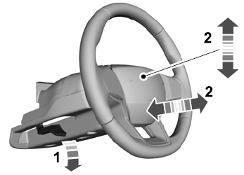
Adjusting the Steering Wheel - Vehicles With: Manual Adjustable Steering Column
WARNING: Do not adjust the steering wheel when your vehicle is moving.
Note: Make sure that you are sitting in the correct position.
Unlock the steering column. Adjust the steering wheel to the desired position.

