Lincoln Aviator: Power Brake Actuation / Description and Operation - Power Brake System - Overview
Electric Brake Boost
Overview
The power assisted brake system utilizes an EBB. The EBB is an integrated function of the ABS / HCU assembly and is controlled by the ABS module. The ABS/ HCU combines the functions of a conventional vacuum booster and ABS module. The ABS module controls and monitors the EBB function and sets Diagnostic Trouble Codes (DTCs) when a fault is present in the system. The IPC illuminates the red brake warning indicator and displays a message in the message center when a fault is present.
 Description and Operation - Power Brake System - System Operation and Component Description
System Operation
System Diagram - Electric Brake Boost
E347819
*.sttxt {
visibility: hidden;
}
*.stcallout {
visibility: visible;
}
HS-CAN3
HS-CAN1
HS-CAN2
1
IPC
2
RCM
3
BCM
4
PCM
5
GWM
6
ABS/EBB
7
Wheel speed
sensors
8
Brake pedal
Item
Description
1
IPC
2
RCM
3
BCM
4
PCM
5
GWM
6
ABS/ EBB
7
Wheel speed sensors
8
Brake pedal
Network Message Chart
Module Network Input Messages - ABS Module
Broadcast Message
Originating Module
Message Purpose
Accelerator pedal position
PCM
This message is first sent to the GWM and then to the ABS module...
Other information:
Lincoln Aviator 2020-2026 Owners Manual: OPERATION INSTRUCTIONS
Read all the instructions before using this product. Supervise this device when in use around children. Do not put fingers into the electric vehicle connector. Do not use this product if the flexible power cord or electric vehicle cable has broken insulation, or any other signs of damage...
Lincoln Aviator 2020-2026 Service Manual: Description and Operation - Rear Climate Control - System Operation and Component Description
System Operation System Diagram Item Description 1 HVAC control module 2 Rear air distribution door actuator 3 Rear temperature door actuator 4 Rear blower motor relay 5 Rear blower motor speed control 6 Rear blower motor 7 Rear air discharge temperature sensor 8 Rear temperature sensor - Second Row 9 Rear footwell air discharge temperature sensor 10 Rear temperature sensor - Third Row 11 IPC 12 GWM 13 FCIMB 14 RACM (Rear Touch screen) 15 APIM ( FDIM Touch Screen) 16 RHVAC control module (Rear Non touch screen) Network Message Charts Module Network Input Messages - APIM Broadcast Message Originating Module Message Purpose Climate control button status HVAC control module This message contains the HVAC climate control settings for the touch screen display...
Categories
- Manuals Home
- Lincoln Aviator Owners Manual
- Lincoln Aviator Service Manual
- Body and Paint
- Garage Door Opener
- Remove and Reinstall the Battery
- New on site
- Most important about car
Remote Control
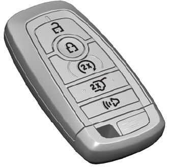
Passive Key

The passive key operates the power locks and the remote start system. The passive key must be in your vehicle to use the push button start.
Note: You may not be able to shift out of park (P) unless the passive key is inside your vehicle.

