
Lincoln Aviator 2020-2026 Service Manual / Chassis / Steering System / Power Steering / Description and Operation - Power Steering - Overview
Lincoln Aviator: Power Steering / Description and Operation - Power Steering - Overview
Overview
The EPAS system provides steering assist by replacing the conventional hydraulic valve system with a steering gear equipped with an integrated electrical motor and PSCM. The motor operation and level of steering assist provided is controlled by the PSCM.
 Description and Operation - Adaptive Steering - System Operation and Component Description
System Operation
System Diagram
Item
Description
1
SECM
2
ECU
3
Private CAN
4
IPMA
5
SIMA
6
PSCM
7
GWM
8
Locking solenoid
9
SASM
10
BCM
11
PCM
12
IPC
13
SUMA
14
RCM
15
Motor
16
HVAC module
17
APIM
Network Input Message Chart
SECM Network Input Messages
Broadcast Message
Originating Module
Message Purpose
Active front steering request
PSCM
Requests steering angle changes for stability control events...
 Description and Operation - Power Steering - System Operation and Component Description
System Operation
System Diagram
Item
Description
1
EPAS gear
2
EPAS motor
3
EPAS position sensor
4
EPAS torque sensor
5
PSCM
6
GWM
7
PCM
8
IPC
9
BCM
10
RCM
11
ABS
12
IPMB
13
IPMA
14
PAM
15
SASM
16
SCCM
17
SUMA
Network Message Chart
PSCM Network Input Messages
Broadcast Message
Originating Module
Message Purpose
Anti-lock brake control activated
ABS module
Informs the PSCM an anti-lock brake event is taking place...
Other information:
Lincoln Aviator 2020-2026 Service Manual: Description and Operation - Information and Entertainment System - Overview
Audio System NOTE: Refer to the Owner Literature for additional details of the audio system. AM/ FM Radio The ACM can operate when the ignition is on or off. The accessory delay feature powers the audio system, after the ignition has been turned off, for a preset time or until a front door is opened...
Lincoln Aviator 2020-2026 Service Manual: Removal and Installation - Front Seat Cushion Adjuster - Vehicles With: Multi-Contour Seats
Removal NOTE: Driver seat shown, passenger seat similar. Remove the front seat cushion cover. Refer to: Front Seat Cushion Cover - Vehicles With: Multi-Contour Seats (501-10A Front Seats, Removal and Installation). Cushion adjuster Remove the front seat cushion blower motor...
Categories
- Manuals Home
- Lincoln Aviator Owners Manual
- Lincoln Aviator Service Manual
- Configuring The Head Up Display
- Description and Operation - Jacking and Lifting
- Interior Lamps
- New on site
- Most important about car
Fastening the Seatbelts
The front outboard and rear safety restraints in the vehicle are combination lap and shoulder belts.
Insert the belt tongue into the proper buckle (the buckle closest to the direction the tongue is coming from) until you hear a snap and feel it latch. Make sure that you securely fasten the tongue in the buckle.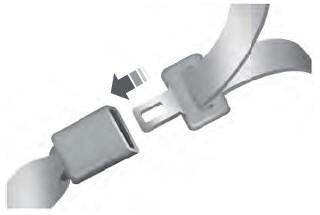

Copyright © 2026 www.liaviator2.com